In this Simple Shock Sensor Alarm Circuit we can feel vibration or shock, which then makes loud sound with piezo buzzer.
Also, we can build this circuit easily and use it at home, in cars and in many other places, as it improves security, helps prevent theft, and detects movement.
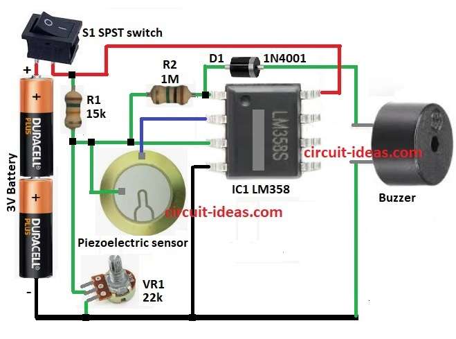
Furthermore, main parts of the circuit is vibration sensor, LM358 IC (op-amp) and piezo buzzer and this article tell how it work, which parts to use and how to change sensitivity.
Circuit Working:
Parts List:
| Components | Values | Quantity |
|---|---|---|
| Resistors | 15k, 1M 1/4 watts | 1 each |
| Potentiometer 22k | 1 | |
| Semiconductors | IC LM358 | 1 |
| Diode 1N4001 | 1 | |
| Piezoelectric Sensor- | 1 | |
| Buzzer | 1 | |
| SPST Switch | 1 | |
| Battery 3V DC | 1 |
Vibration sensor is a main part of this circuit as it feel movement and connect to inverting pin of IC1 op-amp.
Circuit uses 3V battery for power.
Non-inverting pin get voltage from two resistors R1 and R2 which make reference voltage and then op-amp compare sensor signal with this reference.
When sensor feel shock it send signal and if signal is lower than reference IC1 output goes high.
Then switch S1 and turn circuit ON and then IC1 start checking sensor and if there is no shock then inverting pin voltage stay high and output stays low and if shock happen then sensor signal drops.
Now inverting pin is lower than non-inverting with output goes high and then output high turns ON buzzer through diode D1 with and alarm sound.
Finally, when shock stop the sensor signal is normal again with output goes low and buzzer gets OFF.
Formulas with Calculations:
Formulas and Example for Shock Sensor Circuit:
Set Reference Voltage (Vref):
Vref = (R2 / (R1 + R2)) × Vcc
where:
- Vcc is the 3V battery
- R1 is 15k
- R2 is 22k for potentiometer which is adjustable
Change R2 to adjust sensitivity.
Op-Amp Compare Rule:
If V+ > V− → Output = Vcc
If V+ ≤ V− → Output = 0
where,
- V+ is the voltage at non-inverting pin (Vref)
- V− is the voltage from sensor
Example:
Vcc = 3V
R2 = 11k (half of 22k)
Vref = (11k / (15k + 11k)) × 3V
Vref = 1.27V
This 1.27V is the threshold and if sensor signal goes below this then alarm turns ON.
How to Build:
To build a Simple Shock Sensor Alarm Circuit follow the below mentioned steps:
- First, collect all parts as shown in circuit diagram.
- Next, connect pin 1 of IC1 LM358 to anode of diode D1, then connect cathode of D1 to one side of buzzer and other side of buzzer to GND.
- Then connect pin 1 of IC1 to one side of resistor R3 and connect other side of R3 to pin 3 of IC1.
- Now connect pin 2 of IC1 to negative pin of piezo sensor and positive pin of piezo to pin 3 of IC1.
- After that, connect one side of resistor R1 to +3V battery and other side of R1 to pin 3 of IC1.
- Also, connect one leg of VR1 potentiometer to pin 3 of IC1 and second leg to GND.
- Further, connect one leg of S1 switch to pin 8 of IC1 and other leg to + side of 3V battery and connect negative side of battery to GND.
- Lastly, connect pin 4 of IC1 to GND.
Conclusion:
To conclude, Simple Shock Sensor Alarm Circuit is a fun and easy circuit where it feel shock or vibration and makes loud alarm.
We can change sensitivity using the potentiometer which is very useful for many things, as it also show how LM358 IC work as comparator.
Therefore, this project is easy for beginners and DIY people who like to make alarm or security stuff.
Leave a Reply