Smart Vehicle Headlight Brightness Controller Circuit is a cool auto system, it changes headlight brightness auto by checking outside light and also, it helps driver see better and safe at night or in tunnel.
Circuit uses photo-transistor, potentiometer, diode, relay and audio transistor to check light and switch high and low beam easily.
Circuit Working:
Parts List:
| Components | Values | Quantity |
|---|---|---|
| Resistors | 4.7k 1/4 watt | 1 |
| Potentiometer 10k | 3 | |
| Semiconductors | Photo-transistor any PNP | 1 |
| Transistor (Audio Amplifier) BC177 | 1 | |
| Relay 12V SPDT | 2 | |
| Diode 1N4007 | 1 | |
| On/Off Switch | 1 |
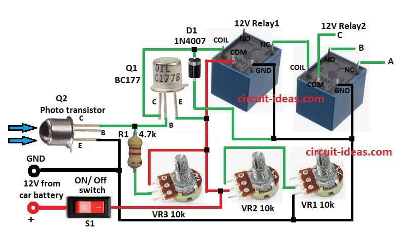
This circuit works with 12V DC power and main part is photo-transistor Q2 which sees outside light.
Q1 is an amplifier transistor and it works with Q2, two relays (relay1, relay2), resistors and pots to control when circuit turns ON.
Then Q2 sees light, more light means more current means lower base voltage for Q1 and Q1 boosts Q2 signal and its output decides if relays turns ON.
Further, VR3 pot changes sensitivity by adjusting Q1.
After that, relays SPDT connect to cars high and low beam lights.
With bright light, Q1 is OFF, relays is OFF and headlights switch to low beam with mode B and C and with low light, Q1 is ON, relays is ON and headlights goes to high beam with mode A.
Finally, diode D1 protects Q1 from back EMF from relays and keeps it safe and with working long.
Formulas:
Photo-transistor Current:
Q2 makes current based on light.
IQ2 = L × S
where,
- L is the light level (lux)
- S is the Q2 sensitivity
Transistor Base Voltage:
Q1 base voltage is:
VB = IQ2 × VR3
Relay Turn-On:
Relay works when Q1 collector current is strong:
IC = (VCC − VCE) / R1
where,
- VCC is the 12V supply
- VCE is the voltage drop across Q1 with 0.2V when ON
Tuning:
So use VR1, VR2, VR3 pots to set how sensitive the system is and when it switches are with high and low beam.
How to Build:
To build a Smart Vehicle Headlight Brightness Controller Circuit we need to follow the below mentioned steps for connections and assembling:
- First, connect collector of photo-transistor Q2 to base of transistor Q1, connect emitter of Q2 to negative (-) of 12V car battery
- Then connect resistor R3 between collector Q2 and base Q1 and also to one leg of VR3, connect other leg of VR3 to one leg of VR2.
- Connect VR2 from VR3 leg to one leg of VR1 and connect other leg of VR1 to negative (-) 12V battery
- After that, connect collector of Q2 to relay1 coil, connect base of Q1 to collector of Q and then connect emitter of Q2 to positive (+) 12V car battery
- Now connect diode D1 cathode to collector of Q1 and anode to negative (-)
- Also, connect GND of relay1 and relay2 to negative (-) battery
- Next, connect NC pin of relay1 to coil of relay2
- Lastly, connect one side of S1 switch between VR3 and VR2 and other side to +12V car battery
Conclusion:
To conclude, this Smart Vehicle Headlight Brightness Controller Circuit, auto changes brightness by outside light, it keeps driver safe with no need of manual switch.
Also, this circuit is cheap, easy and uses photo-transistor and relay.
Therefore, with VR1, VR2, VR3 we can set its sensitivity and when light change with high or low beam.
Leave a Reply