To begin with, this Pressure Sensor Alarm Circuit talks about one electronic device which can feel when pressure goes up or down.
Think of a one special plate like doormat, pressure increases when someone steps on it; or if there is a change in air pressure inside the machine then this device is capable of knowing that.
Also, if pressure become more than limit it give signal like doorbell ring, then this signal can start with an alarm or something so we come to know pressure change has happen.
Circuit Working:
Parts List:
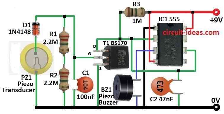
| Components | Values | Quantity |
|---|---|---|
| Resistors | 2.2M 1/4 watt | 2 |
| 1M 1/4 watt | 1 | |
| Capacitors | Ceramic 100nF | 1 |
| Ceramic 47nF | 1 | |
| Semiconductors | IC 555 | 1 |
| MOSFET BS170 | 1 | |
| Diode 1N4148 | 1 | |
| Piezo Transducer | 1 | |
| Piezo Buzzer | 1 |
Above circuit is for pressure sensor alarm circuit and it uses cheap parts, which is easy to find in the market; also working of this circuit is very easy to understand.
When we put 9V battery the circuit turn ON and piezo sounder make small beep and then it waits and if we tap pressure sensor it makes small electric signal and this goes to MOSFET T1 and turn ON the IC1 again.
Then piezo sounder beep again for short time, but how long it beeps depend on R3 and C2 parts.
We can also change piezo sounder with small relay from 6 to 9V and also if we want to control other things and also piezo wafer sensor is easy to buy from good electronics shop.
Finally, T1, R3 and C2 values are not very strict we can change and try what work best for the circuit.
Formula:
IC 555 work like one-shot pulse maker when in monostable mode and we can use simple formula to know how long output pulse stay ON.
Monostable Mode Formula for IC 555:
In this mode how long output stay high depend on one resistor R and one capacitor C which connect to IC 555.
Pulse Time T:
T = 1.1 × R × C
where:
- T is how long pulse stay in seconds.
- R is resistor value in ohms Ω.
- C is capacitor value in farads F.
Inside IC 555 it already gives fixed 1.1 number and above formula make it easy to design monostable circuit and control how long pulse will come.
How to Build:
Below mentioned are the steps to build a Pressure Sensor Alarm Circuit:
- First, take IC1 and connect pin 1 to breadboard negative side of ground.
- Next, connect pin 4 and pin 8 of IC1 to breadboard positive side of power.
- Now join pin 2 and pin 6 of IC1 together and then connect them to positive side using resistor R3 1M .
- Also, connect pin 6 to pin 2 again but this time with capacitor C2 47nF going to ground.
- After that, connect pin 3 of IC1 to ground using piezo buzzer BZ1.
- MOSFET T1 drain connects to positive power, source of T1 connects to ground through resistor R3 1M.
- Lastly, connect pressure sensor piezo transducer between gate of T1 and ground.
Note:
- After we build the circuit test by pressing the pressure sensor and if all parts connect good then piezo will make short beep sound.
- We can also change value of R3 and C2 to make beep sound shorter or longer.
Conclusion:
Overall, Pressure Sensor Alarm Circuit is useful and easy electronic circuit which can feel pressure change and make alarm or other output.
Moreover, people use it in security systems, factories and other places where pressure change need to be checked and action taken.
Leave a Reply