In this article with one clap we can make a Clap Switch Circuit using Speaker as MIC, which can turn something ON or OFF!
Also, we can use normal speaker like microphone which hear the clap sound and then turn switch ON or OFF.
Here, only hand sound controls light or toy, as this is fun and interesting project to try.
Circuit Working:
Parts List:
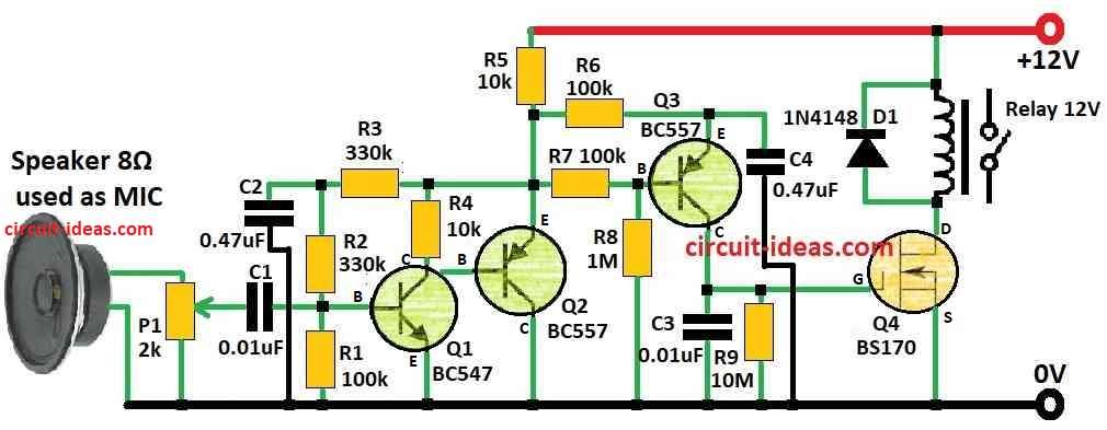
| Components | Values | Quantity |
|---|---|---|
| Resistors (All resistors are 1/4 watt) | 1M | 1 |
| 10M | 1 | |
| 330k | 2 | |
| 10k | 2 | |
| 100k | 3 | |
| Potentiometer 2k | 1 | |
| Capacitors | Ceramic 0.01μF | 2 |
| Ceramic 0.47μF | 2 | |
| Semiconductors | Transistor BC547 | 1 |
| Transistor BC557 | 2 | |
| MOSFET BS170 | 1 | |
| Diode 1N4148 | 1 | |
| Relay 12V | 1 | |
| Speaker 8Ω used as MIC | 1 |
This circuit uses new idea for one coil latching relay, which helps to make easy clap switch with better sound catching; other ways also work but using latching relay make circuit small and simple.
Also, it can turn ON/OFF with big things like 115V or 230V AC load like lightbulb.
Circuit uses very little battery and it uses only 400 microamp and relay coil uses no power when ON or OFF.
One computer speaker act like microphone and it catches clap sound and then sound goes to amplifier with big voltage boost and after that a small transistor detector catches the signal.
Later, we will discuss this amplifier in more detail because this type of detector appears to be a new idea.
Lastly, every part in circuit is special that makes it easy for testing.
High Gain Amplifier:
Speaker give only small signal to about 200 microvolt so we need big boost.
Amplifier uses two parts: Q1 and Q2 and output come from Q2 emitter, also only 400 microamp goes through R5 and that is the the only DC load.
Voltage gain is around 1000 which is good enough for detector and speaker can also hear relay clicking sound.
So we use P1 to set sensitivity if not set it may start looping, so best to keep speaker and relay far from each other.
Battery Use:
Battery is okay for testing only and for regular use better to use wall power supply also 12V power supply also works good.
Noise Detector (Floating):
Only need of one PNP transistor and few parts it is very simple with no need to change anything.
One R-C circuit look at voltage from Q2 which keeps Q3 emitter separate from amplifier output.
R7 and R8 help base of Q3 feel signal better and C4 keeps voltage steady and if we want less sensitivity then do not use R8.
Relay Driver:
Noise detector sends signal to Q4, that is BS170 MOSFET, which needs very small input so it is easy to drive.
R9 take 80 milliseconds to drain C3 and send 2V to Q4 gate which is enough to turn relay ON/OFF
Formula:
When loud sound happens like clap this circuit hear it and turn ON switch or other electric thing, as it uses speaker like microphone (MIC).
Some main formulas help to make this work and here they are with simple explanation:
Making MIC Signal Strong:
To make MIC sound signal louder we must use amplifier, for that use this formula to find gain (Av):
Av = -Rf / Rin
where:
This formula is for inverting amplifier setup.
Setting the Sound Level Threshold:
We need to define the sound level that counts as a “clap,” which is called the threshold voltage (Vth), therefore, we can use a comparator circuit to set the Vth value.
Change reference voltage or resistor values to adjust this level and follow these steps to build good clap switch.
The speaker works like microphone and catches hand clap sound and depending on parts we have or what we need maybe changes design a little.
So for best work choose right resistor values and good quality parts.
How to Build:
To build a Clap Switch Circuit using Speaker as MIC following are the steps for connections and assembling:
How to Connect Latching Relay (Single Coil):
- First, find where to connect relay coil it usually show as coil+ and coil-, so connect coil- to ground and connect coil+ to positive power supply.
Connect Computer Speaker as Microphone:
- After that, use computer speaker as MIC and take output wire from speaker and connect it to input of audio amplifier with transistors Q1 and Q2.
Make the High Voltage Gain Amplifier:
- Now connect parts Q1, Q2, R5 and P1 same like in diagram and also check power connections of amplifier are correct.
Build Floating Level Detector:
- Now put together parts Q3, R7, R8, C3 and C4 as shown and then connect output of high gain amplifier to input of this detector.
Make Relay Driver:
- Use Q4 BS170 MOSFET and R9 to build relay driver and connect output of level detector to input of relay driver.
Power Supply Connection:
- We can use battery or wall power which is up to us and connect power negative (-) to circuit ground and connect power positive (+) to circuits positive rail.
Check and Adjust Circuit:
- Turn ON power and see if circuit works.
- After that, turn P1 to set how sensitive circuit is, if clap is near speaker then relay should turn ON or OFF.
Improve Circuit (If Needed):
- If we want better performance then change some part values or design.
Important Notes:
- Be careful with electric parts; check wires and power before turning ON.
- Use right voltage for safety and if not sure then ask someone who knows electronics for help.
Conclusion:
Overall, this Clap Switch Circuit using Speaker as MIC; also it hears clap sound and turn ON/OFF devices.
Furthermore, the circuit boosts the weak sound from the speaker and turns ON a relay switch to activate devices such as a light or alarm.
Finally, this circuit is good for hands free control and we can change circuit for many uses.
Leave a Reply