This article talks about two easy and Simple Mains Phase Detector Circuit using CMOS ICs like IC 4001 and IC 4060; also they find if mains AC 220V or 120V is present in air.
There is no need to touch the mains, circuit uses antenna to feel mains power in air.
Circuit Working (using IC 4001):
IC 4001 is chip with four 2-input NOR gates, as it help us understand how circuit works and how to makes it.
The steps for the circuit working are shown below:
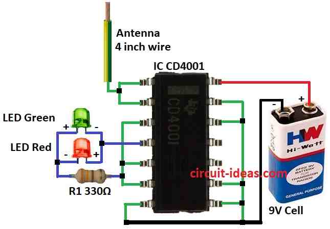
CMOS IC inputs have high impedance so they catch signals from air easily like RF noise and when CMOS input feels AC mains signal it gives strong output from gate.
Furthermore, in this circuit CD4001 inputs sense 50Hz or 60Hz mains AC from air and output shows signal using LEDs.
Parts List:
| Components | Values | Quantity |
|---|---|---|
| Resistors (1/4 watt) | 330Ω | 1 |
| Semiconductors | IC CD4001 | 1 |
| LED Green 5mm 20mA | 1 | |
| LED Red 5mm 20mA | 1 | |
| Antenna 4 inch wire | 1 | |
| 9V Cell battery | 1 |
How to Build:
To build a Simple Mains Phase Detector Circuit using IC CD4001 follow the below mentioned connection process:
- First, join pin 1 and 2 of CD4001 using 4-inch antenna wire.
- Next, connect pin 3, 5 and 6 together and then join resistor R1 to pin 3, 5 and 6.
- Then connect green and red LEDs to pin 4.
- Now pin 7 goes to ground and pin 8, 9, 12, 13 also go to ground.
- After that, pin 14 connect to +9V from battery and battery negative connect to ground.
Circuit Working (using IC 4060):
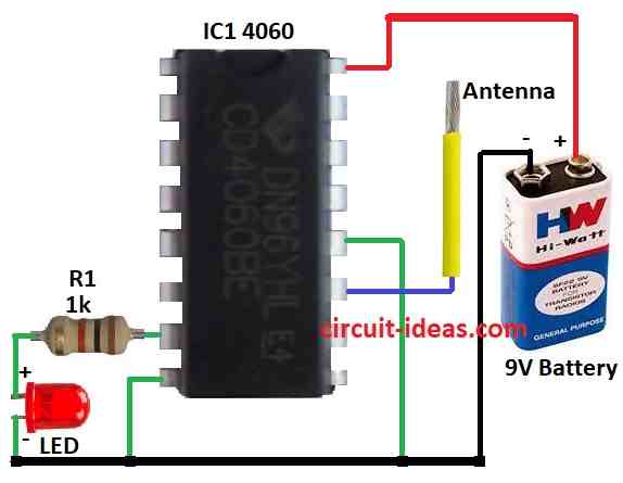
Parts List:
| Components | Values | Quantity |
|---|---|---|
| Resistor (1/4 watt) | 1k | 1 |
| Semiconductors | IC 4060 | 1 |
| LED any 5mm 20mA | 1 | |
| Antenna | 1 | |
| 9V Battery | 1 |
CMOS IC gives reaction when input feel AC mains signal like 50Hz or 60Hz, also signal get stronger inside IC and come out from right gate output.
Here, the circuit uses IC 4060 and pin 11 of the IC detects the 50 Hz or 60 Hz AC mains signal.
If IC senses the signal pin 7 give output and LED turn ON through 1k resistor and then LED show AC mains is present.
Therefore, this circuit is helpful for checking AC mains or special frequencies.
How to Build:
To build a Mains Phase Detector Circuit using IC 4060 follow the below connection steps:
- First, connect pin 7 of IC 4060 to ground through resistor R1 and LED.
- Then pin 8 connect to ground.
- After that pin 11 connect to antenna and pin 12 connect to ground.
- Also pin 16 connect to +9V from battery and battery negative connect to ground.
Safety Measures:
- Always check parts rating and be sure they match our voltage; wear safety gear like insulated gloves and work on non-conductive surface.
- If not sure about electronics stay safe and ask expert for help.
Conclusion:
Simple Mains Phase Detector Circuit using CMOS ICs is cheap and reliable way to find phase changes in AC mains; also these circuits use low power and give good accuracy and is helpful in power control and sync systems.
Moreover, this circuit is easy to use and is efficient, so many people like this method for checking phase angle in power lines.
Leave a Reply