This 3 Band Audio Equalizer Circuit work like small knob to control the music and we can change bass with low sound, mid with voice and instruments and treble with high sound to make music how we like.
So music can sound better for us by depending on type of music or room we are in.
Circuit Working:
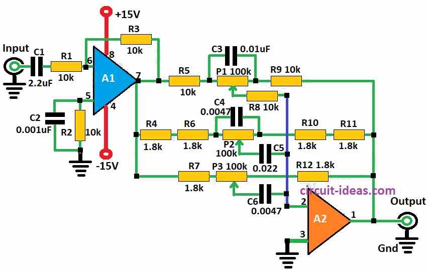
Parts List:
| Components | Values | Quantity |
|---|---|---|
| Resistors | 10k 1/4 watt | 6 |
| 1.8k 1/4 watt | 6 | |
| Potentiometer 100k | 3 | |
| Capacitors | Ceramic 2.2µF | 1 |
| Ceramic 0.001µF | 1 | |
| Ceramic 0.01µF | 1 | |
| Ceramic 0.022µF | 1 | |
| Ceramic 0.0047µF | 2 | |
| Semiconductor | IC LM358 | 1 |
To begin with, this active filter uses LM358 op-amp from National Semiconductors is to make 3 band equalizer circuit for bass, mid and high sound.
Here, we can also use the LM833 op-amp because it has low noise, wide bandwidth and a fast signal response with a high slew rate.
Also, output of circuit is DC coupled but small DC changes on 100k pots in op-amp A2 feedback line maybe need a coupling capacitor.
Below are the technical details for this 3 band equalizer:
Bass cut-off: 200 Hz
Mid sound is bandpass is around: 1 kHz
High cut-off: 2 kHz
Equalizer range go up to around 15 dB max and when pot is at center and the noise reduces by around 90 dB with 1 MHz bandwidth and 0 dB gain.
Also. gain can change using R2 with formula given below.
Formula:
Gain Formula for 3 Band Audio Equalizer Circuit:
In this circuit we can use op-amp in non-inverting style and for this we can use this formula:
Vu = R2 / R1
Here is how R1 and R2 connect:
R1 connects between op-amps ground and inverting input and R2 connects between op-amps output and inverting input.
What they do:
- R2 is usually a variable resistor a potentiometer and it let us change the gain of amp.
- R1 fixed resistor and it work together with R2 to set gain.
- Vu means voltage gain of amplifier.
But in our circuit diagram formula is a little different:
Vu = R3 / R2
We use this to find gain of op-amp in our equalizer circuit.
How to Build:
To build a 3 Band Audio Equalizer Circuit follow the below mentioned assembling steps:
Gather all the components:
- Be sure all parts are ready and check all needed components are present.
- First, put LM358 op-amp on PCB board.
Give power to op-amp:
- Next, pin 4 is for negative power and pin 8 is for positive power.
- Then connect Pin 3 of IC to ground.
- Use schematic to connect all parts like resistors, capacitors and pots P1, P2, P3 and also use right values for each one.
Connect Inputs and Outputs:
- Now for bass, mid and high bands give input signal to pot P1, P2 and P3.
- Output from each band connect to one point which is the summing point where R7, R8 and R9 meet.
Testing the Circuit:
- Finally, after connecting everything, give an audio input from a music player to the equalizer and connect the equalizer output to an amplifier or headphones.
- Then turn ON the power and try moving each pot P1, P2, P3 to hear how sound change.
Tuning and Adjusting:
- Also, we can change resistor, capacitor and pot values to get better sound or different frequency and to see frequency response better use tools like oscilloscope or spectrum analyzer.
Important Note:
- Making this circuit need some basic electronics knowledge and soldering and if anyone do not know how to design this circuit ask someone who knows electronic expert for help.
Conclusion:
Overall, we can build a 3 Band Audio Equalizer Circuit using op-amps, resistors and capacitors, as it helps adjust the bass, mid, and treble levels in an audio signal.
Furthermore, by choosing right values for parts we can control which sound range to change and this way we can make the audio sound how we like for different needs or choices.

Leave a Reply