In this Simple Room Ionizer Circuit, a machine called a room ionizer helps clean the air in a room and it also creates small electric particles called ions.
Furthermore, these ions catch smoke, dust and bad things in air and ionizer use special electric way to make these ions.
Like when we press one side of a balloon hard and the electric charge becomes uneven on both sides, the Cockcroft Walton ladder helps create this effect.
Circuit Working:
Parts List:
| Components | Values | Quantity |
|---|---|---|
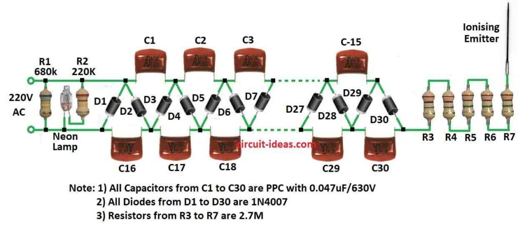
| Resistors | 680k 1/4 watt | 1 |
| 220k 1/4 watt | 1 | |
| 2.7M 1/4 watt | 5 | |
| Capacitors | PPC 0.047µF 630V | 30 |
| Semiconductors | Diodes 1N4007 | 30 |
| Neon Lamp | 1 | |
| Ionizing Emitter (Needle) | 1 |
A room ionizer uses high voltage to work and it often uses a special part called a Cockcroft Walton ladder network, which creates a large voltage between two metal points like electrodes.
Hence, because of this high voltage air get small sparks like corona discharge and this make ions in air.
Also, these ions go and stick with dust or allergy things in air and they give charge to those bad things; then charged dust goes and stick to walls or other surfaces.
So air become clean and better to breathe.
How circuit work:
Main part of this DIY ionizer is Cockcroft Walton ladder network, it take normal home voltage and make it very high like 10,000 volts (10 kV).
Also, each time power goes up and down from the mains cycle then two groups of capacitors send charge.
Then the voltage slowly rises higher and higher because of the rectifiers and this circuit helps build a good room ionizer.
In theory, every capacitor should hold full mains voltage, but in actual life leakage and corona discharge stop it from working perfect.
Actually circuit give about 4,000 volts (4 kV) which is best for ionizer and lower voltage is still good for making ions but if voltage go too high it make ozone instead which is not always good.
But if someone touches the metal point the emitter then the voltage drop a lot.
Be careful:
Even if it look safe each capacitor can still give a shock so we should be careful; also while testing circuit do it safely.
Furthermore, after unplug, capacitors still hold power for some time, shock may not hurt healthy person but people with heart problems or pacemaker must be very careful.
Hence, to make it safe, after use we should touch metal point with mains plug for few seconds and this will make extra charge go away through the circuits diode path.
Formula:
In a Walton Cockcroft Voltage Multiplier, we find the normal DC output voltage (Vdc) by multiplying the peak input voltage (Vmax) by the number of steps, so for example, in the circuit above the maximum voltage is:
Vdc = 3 × 2 × Vmax
Here:
- Vdc means constant DC voltage.
- Number 3 maybe shows part of the design or how the circuit modifies it.
So they multiply by 3 using this math:
1.56 × 2 = 3.12 and
1 ÷ 0.637 = 1.56
Also, 2 × 2 is another way to guess voltage drop or errors in actual circuit.
More correct ways to find Vdc:
If circuit uses full wave rectifier and perfect parts, then voltage loss from diodes is:
Vdc = Vmax × 0.637 – diode loss
For half wave rectifier it is simple:
Vdc = Vmax × 0.637
Also, remember these are just best ideas, but in real life other things like bad parts or heat may change the real Vdc value.
How to Build:
Below mentioned are the following steps required for building a Simple Room Ionizer Circuit:
Build the Circuit:
- Make Cockcroft Walton ladder network on circuit board.
- Look at circuit diagram in the article for help.
- Choose right resistor, capacitor and diode based on how much voltage we want.
Assemble the Circuit Board:
- Put all parts on board like shown in diagram and before soldering check all wires and parts are in correct place and tight.
Connect High Voltage Parts:
- Now connect high voltage resistors and transistors to circuit and these will help to control big voltage in safe way.
Power Source:
- Connect the circuit to power and power must give enough voltage for the Cockcroft Walton ladder to work.
Safety Precautions:
- When working wear gloves and safety glasses and always check circuit is safe so no shock happen.
Testing:
- Turn ON the circuit and watch output voltage and use high voltage meter or multimeter that can measure big voltage.
Changes:
- Also, if voltage is not right then change the circuit a bit and do it slow and carefully and watch everything closely when fixing.
Safety When Using:
- After circuit working is OK follow safety rules to use it and even after we unplug be careful capacitors still hold power which can give a shock.
Conclusion:
Overall, Simple Room Ionizer Circuit can help clean air but results can be different; also ozone can come sometimes which is not always good.
People with health problems must use ionizer carefully, if required it is better to ask expert before using.
Leave a Reply