Neon light look very nice but it needs much electricity to work; this Neon Tube Flasher Circuit show how to make special circuit to turn ON and OFF neon light using small battery with low voltage DC.
WARNING: Making high voltage circuit can be dangerous, so do this only when adults are watching.
What is a Neon Tube Flasher Circuit:
Neon tube flasher circuit is small electronic circuit that makes neon light blink ON and OFF with set speed; also people use neon flasher for decoration, ads or for cool display ideas.
Circuit Working:
Parts List:
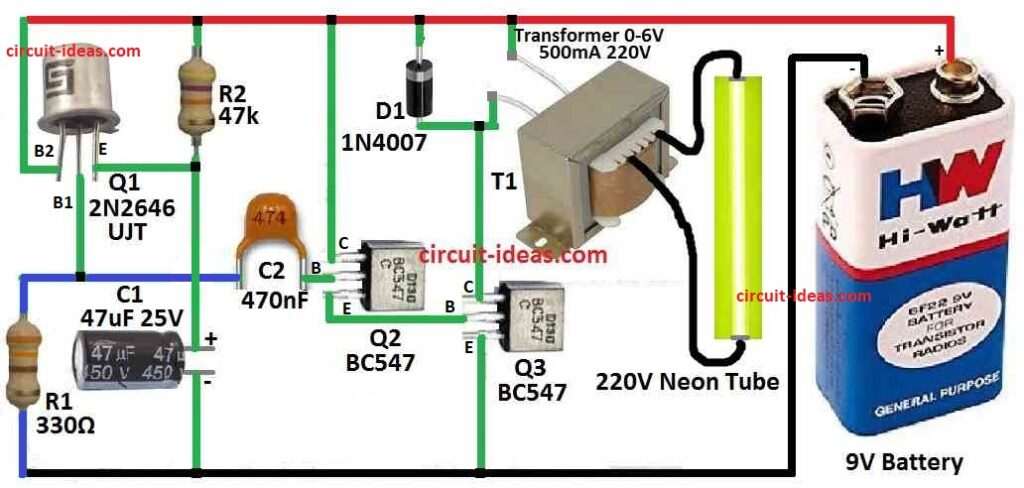
| Components | Values | Quantity |
|---|---|---|
| Resistors | 47k CFR 1/4 W | 1 |
| 330Ω CFR 1/4 W | 1 | |
| Capacitors | Ceramic 470nF | 1 |
| Electrolytic 47µF 25V | 1 | |
| Semiconductors | Transistors BC547 | 2 |
| UJT 2N2646 | 1 | |
| Diode 1N4007 | 1 | |
| Transformer 0-6V 500mA 220V | 1 | |
| Neon Tube 220V | 1 | |
| Battery 9V | 1 |
To get enough voltage to start neon tube normal step-down transformer 240 to 6.3V is connected in reverse; also this will give right voltage for circuit.
Next, when using 9V battery, circuit use very little power only 1 to 2 milliamp, so it is work good and it saves battery.
Also, the main part is unijunction transistor Q1 which works like relax oscillator and R2 and C1 parts work together to set the blink speed.
Then Q3 transistor turn ON fully because of pulses from Q1 and these pulses go through Q2 and when this happen current go high in 6.3V winding of transformer.
Moreover, Q3 gives strong voltage to secondary transformer which makes neon tube blink fast and also to stop damage diode D1 is added to save transistors from high voltage shock from transformer.
Formulas:
Using UJT to find relaxation oscillator circuits blinking speed for frequency:
Formula:
f = 1 / ( η * R * C)
- f is how fast it blinks in Hz.
- η (eta) is standoff ratio of UJT which is normally between 0.4 to 0.7 and can change by UJT type.
- R is resistance in ohms and in this circuit it is 47k.
- C is capacitor size in farads and here it is 47µF.
How to use formula:
Find η (eta):
Check the UJT datasheet it tells eta value and if no datasheet then guess between 0.4 and 0.7 but result may not be so correct.
Put values in formula:
Use known R, C and eta to get rough frequency number.
Important Notes:
Real circuit might blink different speed because of part differences, eta change or other things and if we want more correct result use SPICE simulator to test circuit.
We can also check UJT oscillator examples and notes for more help.
Note: Some UJT models behave little different so always check if possible.
How it is Build:
To build a Neon Tube Flasher Circuit follow the below steps for connections:
- First, put unijunction transistor Q1 on PCB.
- Then add resistors R1, R2 and capacitor C1 which make the relaxation oscillator, which gives correct blinking speed.
- Next, connect transistor Q2 to get the pulse from Q1 and this will help connect to oscillator.
- After that join transistor Q3 with Q2 and this will let Q3 go into full ON (saturation) when it get pulse.
- Now connect the step down transformer in reverse which will give high voltage to neon tube and to save transistors from high voltage shock, so carefully put diode D1 in circuit.
- Then connect neon tube in right place and this will give flashing light when circuit works.
- At last join 9V battery to whole circuit this will make current flow correct.
Conclusion:
Overall, now we make cool Neon Tube Flasher Circuit which works good with low voltage battery and can be used in many fun ways.
Leave a Reply