To begin with, we use piezoelectric transducers in a footstep power circuit because they convert foot pressure into small electrical power.
Furthermore, piezoelectric effect means crystal which makes electricity when press or stress happen and if we press special crystal a small current comes out.
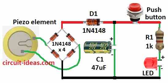
Hence, Simple Footstep Electricity Generator Circuit uses parts like piezo transducer, bridge rectifier, capacitor, resistor and LED.
Circuit Working:
Parts List:
| Components | Values | Quantity |
|---|---|---|
| Resistor 1/4 watt | 1k 1/4 watt | 1 |
| Capacitor | Electrolytic 47μF 25V | 1 |
| Semiconductors | Bridge Rectifier 1N4148 | 4 |
| Diode 1N4148 | 1 | |
| LED red 5mm 20mA | 1 | |
| Push button | 1 | |
| Piezo element | 1 |
Piezo sensor is a heart of the circuit:
Crystals such as quartz form the piezo sensor.
When we press it, it generates a small amount of electricity like a tiny power plant without fuel and inside the crystal, mechanical stress produces electrical energy
Why we need bridge rectifier AC to DC:
Piezo make AC power go forward and back, but LED need DC power one way; so we use bridge rectifier to change AC to DC, like gatekeepers it lets current go only one way.
Capacitor for storing energy:
Each step give small spark of power and capacitor hold this power like mini battery and helps LED stay ON longer.
Button and LED work together:
LED is star of show! so when we press a button capacitor gives stored power to LED and then LED lights up but because capacitor is small an LED shine only for short time.
Make LED stay ON longer:
To keep LED on more time it use bigger capacitor but take more time to charge, or it uses more piezo sensors in series to get more power.
Resistor and diode keep things safe:
Diode stops power going wrong way back to sensor and resistor control how much current goes to LED and both helps to protect a circuit.
Why capacitor is important:
If we connect LED straight to sensor it blink only fast, so there is no steady light but capacitor stores power and give smoother light.
Formulas:
Use these formulas to make Footstep Power Circuit with Piezo:
LED Current Formula with ohms law:
To find the current (I) when we press the button:
I = (Vcc − VLED) / R
where:
- Vcc is the power supply from 5V or 9V
- VLED is the LED drop to around 2V for red LED
- R is the resistor for example 1k
Note:
Resistor must keep current safe to around 20mA for normal LED and Vcc must be enough to light LED.
How circuit works:
When we step the piezo changes pressure into electricity and when we press button and the stored energy then goes to LED and LED light up for short time.
How to Build:
To build a Simple Footstep Electricity Generator Circuit using Piezo Transducer following are the below mentioned steps:
- First, connect C1 between positive supply and ground
- Next, connect D1 and push button in series from positive supply
- After that, connect R1 and LED in series from positive supply to ground
- Now build bridge rectifier using 4 × 1N4148 diode and then connect piezo wires to AC input of bridge rectifier
Safety Tips:
- Circuit is in low voltage, low current and so mostly its safe; still take care and follow steps to stay safe and enjoy learning.
Conclusion:
To conclude, this Simple Footstep Electricity Generator Circuit using Piezo Transducer make small electric when we step on piezo.
Moreover, AC power changes to DC with rectifier and capacitor store this power.
Hence, when we press a button the power goes to LED and LED lights up and this shows how daily motion can give clean energy.
Leave a Reply