This 220V AC to DC Voltage Converter is small circuit like small adapter for our devices.
Wall socket gives AC power but many electronics like phone, laptop, LED light they need DC power to work; hence, this circuit work like translator, it take big AC power from wall and change it to smooth DC power so our device can use it.
Circuit Working:
Parts List:
| Components | Values | Quantity |
|---|---|---|
| Resistors (All resistors are 1/4 watt unless specified) | 10k 3W | 1 |
| 7.5k | 1 | |
| 1M | 1 | |
| 100k | 1 | |
| 10k | 1 | |
| 1.2k | 1 | |
| 100k 1W | 2 | |
| Capacitors | Electrolytic 10µF 25V | 1 |
| Electrolytic 470µF 25V | 1 | |
| Electrolytic 330µF 250V | 2 | |
| Semiconductors | IC MC34161 | 1 |
| Triac TIC216 | 1 | |
| Bridge rectifier 1N4007 | 4 | |
| Zener diode 12V 5W | 1 | |
| Fuse 3AF | 1 |
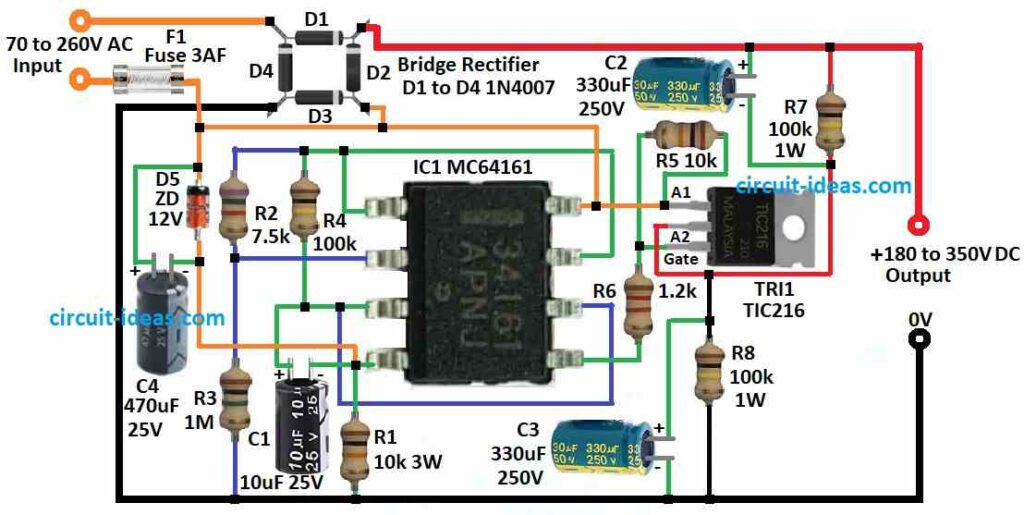
To begin with, this circuit changes AC voltage from 70V up to 260V into DC voltage between 180V and 350V, also it can work with both 110V and 220V systems.
Furthermore, it uses one chip called MC34161 and this chip work like voltage doubler when AC voltage is low and like normal rectifier when voltage is high.
Inside this chip is pin 1 which give 2.54V power and pin 2 checks signal and compare it with 1.27V.
One Zener diode D5, resistor R1 and capacitor C4 make 12V power for the chip to work and capacitors C2 and C3 must be strong and can handle more than 250V.
The chip control triac so circuit can work like full wave doubler or full wave bridge which depend on AC input.
Also, channel 1 look at negative side of AC voltage.
If the voltage drops below 150V, the circuit waits for a short time, which the 100 kΩ resistor and 10µF capacitor set and then switches to voltage-doubler mode.
When the voltage rises above 150 V again, the circuit immediately switches back to full-wave bridge mode.
Warning: This circuit makes very high voltage and can be very dangerous or even deadly so be very careful if anyone touches or work with it.
Formulas:
Manufacturers mainly designed the MC34161 for PWM control, but in some cases, it can also function as a voltage doubler or a standard rectifier.
Below are formulas for both:
Voltage Doubler:
Vout = 2 × Vpeak – diode voltage loss
here,
- Vpeak is the highest point of AC voltage.
Normal Rectifier:
Vout = Vpeak – diode voltage loss
- Again Vpeak is the AC voltage peak value.
Note:
It is better to use special rectifier circuits like diode bridge or full wave rectifier for this kind of job, as they give better performance and work more efficient.
Also, the MC34161 works best for PWM control because designers created it specifically for that purpose.
How to Build:
To build a 220V AC to DC Voltage Converter Circuit we need to follow the connections steps mentioned below:
Safety First:
- First, before starting be sure power is OFF and unplugged and then use tools with insulation and work in dry place only.
Circuit Assembly:
- First, put all parts on PCB as per circuit diagram and then solder resistors, capacitors, diodes and IC in right places.
- Then use wires to connect all parts and check the polarity and connection is correct.
Testing and Adjustment:
- Before connecting to AC power check all parts and wire again for mistakes and use multimeter to check short circuit and insulation.
- Then give power and check output voltage with multimeter and if required make small changes.
Safety Precautions:
- Put the circuit inside good cover so no one touches high voltage by mistake and add fuse or circuit breaker in input wire for safety from too much current.
Final Testing:
- After we complete and test everything, connect the circuit to AC power, apply a load and check whether it provides the correct DC voltage under load.
Important Note:
- Be careful with high voltage its very dangerous and if not sure how to do something better try to ask help from expert or trained person.
Conclusion:
A Simple 220V AC to DC Voltage Converter Circuit is very important part in electronics, as it changes high voltage AC from 220V power into stable DC power at needed voltage.
Also, this help electronic devices work good and safe.
Leave a Reply