The AC to DC bridge voltage doubler is a simple power supply circuit that converts a low AC input voltage into a higher DC output voltage; for example, a 9 V AC input can produce approximately 18 V to 25 V DC, depending on the load and circuit components.
Therefore, this circuit is useful when we need a high voltage but the transformer provides only a low voltage, also it costs little and is easy to build.
Circuit Working:
Parts List:
| Components | Values | Quantity |
|---|---|---|
| Capacitors | Electrolytic 470uF 63V | 2 |
| Semiconductors | Transformer 0V-9V AC secondary, 220V primary | 1 |
| Bridge diodes 1N4007 | 4 |
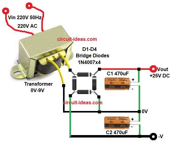
To begin with, the above circuit uses a step down transformer 220V AC to 9V AC, four bridge diodes and two electrolytic capacitors.
First, 220V AC mains goes to transformer primary and this transformer reduces voltage to 9V AC at secondary.
Then 9V AC goes to bridge network made by four diodes and this bridge works like rectifier and voltage doubler together; also C1 and C2 are filter capacitors and they charge on alternate half cycles, after that their voltages add in series.
Therefore, output voltage becomes nearly double of AC peak voltage and finally we get DC output across Vout and GND.
Formula with Calculation:
First find peak voltage from AC RMS voltage.
Vpeak = Vrms x 1.414
If transformer secondary is 9V AC then:
Vpeak = 9 x 1.414
Vpeak = 12.726V
Now voltage doubler output is approximately:
Vout = 2 x Vpeak
So,
Vout = 2 x 12.726
Vout = 25.452V
Now subtract diode drops, as each diode drop is about 0.7V (silicon diode) and two diodes conduct in each half cycle.
Total diode drop = 0.7 x 2
Total diode drop = 1.4V
So practical DC output is:
Vout practical = 25.452 – 1.4 = 24V
Vout practical approximately is 24V but under load the voltage may reduce more.
How to Build:
To build a AC to DC Bridge Voltage Doubler Power Supply Circuit follow the below connection steps:
- First, gather all the circuit parts as shown in diagram above.
- Then transformer primary side connect 220V AC mains to primary pins carefully and secondary side one pin goes to bridge diode input point and second pin goes to 0V.
- After that, diodes D1 to D4 connect as per circuit diagram.
- Now capacitors C1 positive side connect to to positive output and negative of C1 connect to 0V.
- Finally, connect positive of C2 to 0V and negative of C2 goes to -V.
Conclusion:
Overall, AC to DC Bridge Voltage Doubler Power Supply Circuit is simple and useful project, as it increases DC voltage without using high voltage transformer.
Therefore, it saves cost and space, however it is good only for low current applications and if load current is high then voltage drop will be more.
So use this circuit for small current power supply needs like small projects and experiments.

Leave a Reply