• Skip to primary navigation
  • Skip to main content
  • Skip to primary sidebar

Circuit Ideas for You

Get free circuit ideas online.

  • Home
  • Privacy Policy
  • About
Home » Simple Phone Transmitter Circuit

Simple Phone Transmitter Circuit

Last updated on 4 June 2026 by Admin-Lavi Leave a Comment

Simple Phone Transmitter Circuit uses few parts, as it take sound from phone talk and changes to signal and also signal goes far using antenna.

Furthermore, this circuit is easy to make and works well with landline phone.

Circuit Working:

Simple Phone Transmitter Circuit Diagram

Parts List:

ComponentsValuesQuantity
Resistors10k, 47k, 330Ω (1/4 watt )1 each
CapacitorsCeramic 47pF3
SemiconductorsTransistor BC5471
Diodes 1N41484
Inductor Coil inductor, 7 turns using 0.5mm wire, 3mm dia.1

This device take voice from phone talk and it changes voice into signal for other electronics; also, it work only in short distance and uses phone wire like antenna.

Below is how circuit work:

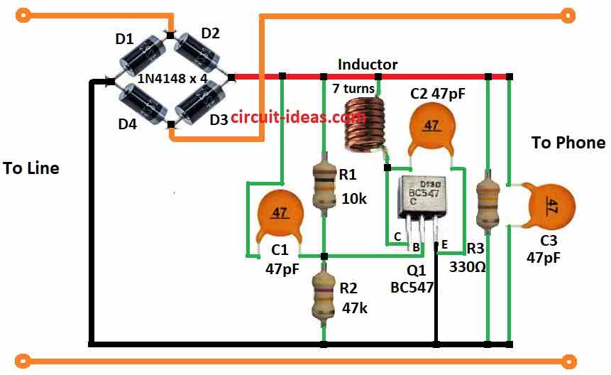
Four diodes D1 to D4 make bridge and it change AC to DC for power.

Transistor Q1 with R1, C1 and coil make oscillator and this oscillator give high frequency signal based on coil and C1.

C2 send audio signal to base of Q1 and audio change the high frequency signal (modulation).

Q1 and coil make signal strong and send out and C3 help to adjust signal frequency.

Formulas:

Colpitts oscillator made by transistor Q1, R1, C1 and coil L1, as it give high frequency signal.

Formula for frequency is:

f = 1 / (2π * √(L1 * (C1 + C2)))

where:

  • f is frequency in hertz Hz
  • L1 is coil value in henrys H
  • C1 and C2 are capacitor values in farads F

Note:

This formula work for ideal parts but real parts are not perfect so frequency may be little different; hence, for better result use SPICE software or also count transistor base capacitance.

How to Build:

To build a Simple Phone Transmitter Circuit follow the below mentioned steps for connections:

  • First, connect Q1 collector to (+) supply through coil, connect Q1 base to capacitor C1 and then connect Q1 emitter to ground.
  • After that, put R1 and R2 in series from (+) to (–) supply.
  • Now connect one side of C2 to coil and other side to Q1 emitter.
  • Then connect C3 from (+) to (- ) supply and also connect R3 from (+) to (–) supply.

Caution:

  • Be careful while using radio transmit device without license may be illegal and check the local rules in your areas

Conclusion:

Overall, Simple Phone Transmitter Circuit changes voice to electric signal to send, but it is not the same like radio transmitter for sending phone talk.

So be careful to not mix both.

Filed Under: DIY Projects, Mini Projects, Oscillator Circuits, Transmitter Circuit

About Admin-Lavi

Lavi is a B.Tech electronics engineer with a passion for designing new electronic circuits. Do you have questions regarding the circuit diagrams presented on this blog? Feel free to comment and solve your queries with quick replies

Previous Post: « Mobile Phone Detector Circuit using Transistors
Next Post: Simple IC 555 Oscillator Circuits »

Reader Interactions

Leave a Reply Cancel reply

Your email address will not be published. Required fields are marked *

Primary Sidebar


Categories

  • 555 Timer Projects (59)
  • Alarm Circuits (68)
  • Amplifier Circuits (90)
  • Arduino Projects (103)
  • Audio Circuits (179)
  • Automation Circuits (49)
  • Automobile Circuits (28)
  • Battery Charger Circuits (86)
  • DIY Projects (214)
  • Free Energy (13)
  • Heater and Temperature Controllers (29)
  • High Voltage (23)
  • Hobby Circuits (106)
  • Indicator Circuits (60)
  • Inverter Circuits (19)
  • IoT projects (1)
  • LDR Circuits (37)
  • LED and Lamps (183)
  • Meters and Testers (39)
  • Mini Projects (166)
  • Motor Controllers (25)
  • Oscillator Circuits (57)
  • Power Supply Circuits (202)
  • Remote Control Circuits (10)
  • Renewable energy (1)
  • Security and Protection (78)
  • Sensors and Detectors (195)
  • Solar Circuits (31)
  • Timer Circuits (56)
  • Transistor Circuits (150)
  • Transmitter Circuit (20)
  • Tutorials (9)
  • Voltage Regulator (19)
  • Water Level Controller (10)

Recent Posts

  • Low Current Controlled Battery Charger Circuit using LM723 IC
  • 741 Op-Amp Treble Booster Circuit
  • Simple Diode and Transistor Based Audio Limiter Circuit
  • Simple 500mW Speaker Driver Circuit
  • Easy DIY LM386 Audio Amplifier Circuit

Recent Comments

  1. Tony Gallegos on NTC Thermistor Based Temperature to Voltage Converter Circuit
  2. colin on Simple Single Transistor Audio Amplifier Circuit
  3. How to Make a Bird Chirping Noise Easily on Chirping Bird Sound Generator Circuit
  4. Transistor Based Medium Impedance Preamplifier Circuit - Circuit Ideas for You on Low Impedance Input Transistor Preamplifier Circuit
  5. Admin-Lavi on Alternate Red Green LED Flasher Circuit

Copyright © 2026 | New Circuit Ideas