PWM LED Ramping Circuit (Slow Bright, Slow Fade) make LED light go bright slowly and with not sudden ON/OFF, as this circuit is good for signal, decoration and for soft light.
Also, it uses 2× IC 555, LM393, 2N7000 MOSFET for smooth change and the circuit works best with 3 to 12V power with 6V is best.
Circuit Working:
Parts List:
| Components | Values | Quantity |
|---|---|---|
| Resistors (All resistors are 1/4 watt unless specified) | 47k | 1 |
| 1M | 1 | |
| 10k | 1 | |
| 180Ω | 1 | |
| Capacitors | Ceramic 0.001µF | 1 |
| Electrolytic 1µF 25V | 1 | |
| Semiconductors | IC 555 | 2 |
| IC LM393 | 1 | |
| MOSFET 2N7000 | 1 | |
| LED any 5mm 20mA | 1 |
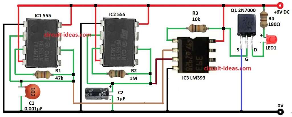
IC1 555 timer generates a square-wave clock signal at Pin 3, and R1 and C1 show its frequency.
IC2 555 timer generates a ramp signal, while C2 charges and discharges slowly and R2 and C2 control the ramp speed.
Then IC3 LM393 compare ramp with fixed voltage which gives PWM signal and after that, Q1 2N7000 MOSFET act as switch and control LED brightness
Finally, PWM make LED slow bright and slow fade.
Formulas with Calculations:
The following formulas and calculations explain the PWM LED Ramping Circuit (Slow Bright, Slow Fade).
IC1 555 (square wave):
f = 1.44 / (R1 × C1)
R1 = 47k. C1 = 0.001µF ( = 1 × 10⁻⁹ F).
f = 1.44 / (47000 × 1e-9) = 30,638 Hz = 30.6 kHz.
IC2 555 (ramp time):
t = R2 × C2
R2 = 1M, C2 = 1µF ( = 1 × 10⁻⁶ F).
t = 1,000,000 × 0.000001 = 1 second.
MOSFET LED current:
I_LED = (V_supply − V_MOSFET) / R4
V_supply = 6 V, V_MOSFET = 0.2 V, R4 = 180 Ω.
I = (6 − 0.2) / 180 = 5.8 / 180 = 0.03222 A = 32.2 mA
How to Build:
To build a PWM LED Ramping Circuit (Slow Bright, Slow Fade) follow below steps for connection:
- First, take all parts from circuit diagram.
Connection of IC1:
- Next, connect IC1 pin 1 to GND.
- Then connect IC1 pin 2 to IC1 pin 6 and connect C1 between IC1 pin 2 and GND.
- Now connect IC1 pin 3 to IC1 pin 6 through R1.
- Further, connect IC1 pin 4 and pin 8 to +V.
IC2 Connection:
- First, connect IC2 pin 1 to GND and then IC2 pin 2 go to IC1 pin 6 and also C2 goes between IC2 pin 2 and GND.
- Also, IC2 pin 3 go to IC2 pin 6 through R2.
- Now, IC2 pin 4 and pin 8 go to +V.
Connection of IC3:
- Next, IC3 pin 1 go to MOSFET Q1 gate.
- Then IC3 pin 2 go to IC1 pin 6 and also IC3 pin 3 go to IC2 pin 6.
- Now connect IC3 pin 4 to GND.
- Further, connect IC3 pin 8 to +V and also connect R3 from IC3 pin 8 to IC3 pin 1.
- Also, MOSFET drain go to LED cathode and LED anode connect to one side of R4 and other side of R4 connects to +V.
- Finally, MOSFET source connects to GND.
Conclusion:
To conclude, this article for PWM LED Ramping Circuit (Slow Bright, Slow Fade) make LED slow bright, slow fade and it use 555 timers, comparator, MOSFET for smooth work.
Also, if require we can change R, C values to change fade speed for many projects.
Leave a Reply