• Skip to primary navigation
  • Skip to main content
  • Skip to primary sidebar

Circuit Ideas for You

Get free circuit ideas online.

  • Home
  • Privacy Policy
  • About
Home » Simple Wire Loop Security Alarm Circuit

Simple Wire Loop Security Alarm Circuit

Last updated on 22 June 2026 by Admin-Lavi Leave a Comment

A simple wire loop alarm is a small security circuit that uses a thin wire as a sensor loop and if someone cuts or opens the loop, the buzzer sounds.

Also, it works on 9V battery, needs few parts, is cheap and easy to make.

Circuit Working:

Simple Wire Loop Security Alarm Circuit Diagram

Parts List:

ComponentsValuesQty
Resistors4.7M 1/4 watt1
100k 1/4 watt1
Capacitor 0.1µF1
SemiconductorsN-MOSFET 2N70001
Buzzer 9V1
Wire loop sensor thin insulated wire1
Battery 9V PP31

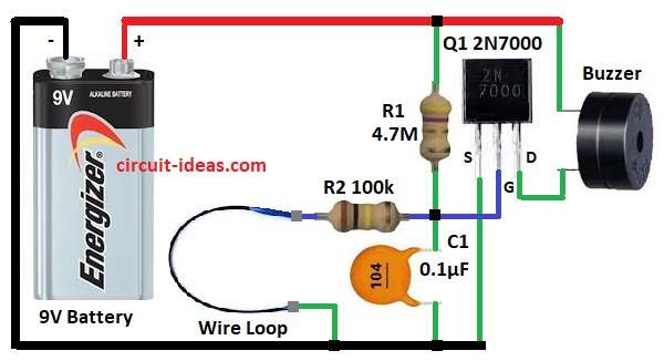
This is simple wire loop alarm circuit using MOSFET 2N7000, buzzer and few parts.

Normally, the wire loop and the 100k resistor R2 connect the gate of Q1 to ground and if someone cuts the wire loop, Q1 turns ON and the buzzer sounds.

Then circuit uses very less current in standby so battery lasts long and the whole circuit runs on 9V PP3 battery.

How to Build:

To build a Simple Wire Loop Security Alarm Circuit follow the connections steps below:

  • First, take all parts as in circuit diagram.

Battery connection:

  • Then battery 9V positive goes to R1 and buzzer and battery negative goes to ground.

Resistor and capacitor connection:

  • After that, R1 goes from battery positive to MOSFET gate.
  • Now R2 goes between wire loop and gate and then C1 goes between gate and ground.

Wire loop connection:

  • Further, wire loop goes between R2 and ground.

MOSFET connection:

  • Now MOSFET gate connects with R1, R2 and C1, source pin goes to ground and drain pin goes to buzzer and battery positive.

Buzzer connection:

  • Finally, buzzer one side connects to battery positive and other side to MOSFET drain.

Conclusion:

To conclude, this Simple Wire Loop Security Alarm Circuit is useful for security, it can protect doors, windows or valuable things.

We can easily hide the loop wire and the buzzer sounds immediately if someone cuts or opens the loop; therefore, beginners can build this circuit easily.

Filed Under: Alarm Circuits, Hobby Circuits, Mini Projects, Security and Protection

About Admin-Lavi

Lavi is a B.Tech electronics engineer with a passion for designing new electronic circuits. Do you have questions regarding the circuit diagrams presented on this blog? Feel free to comment and solve your queries with quick replies

Previous Post: « Buzzer Alert at 0°C Indicator Circuit
Next Post: 555 IC Based Schmitt Trigger Circuit »

Reader Interactions

Leave a Reply Cancel reply

Your email address will not be published. Required fields are marked *

Primary Sidebar


Categories

  • 555 Timer Projects (123)
  • Alarm Circuits (75)
  • Amplifier Circuits (92)
  • Arduino Projects (103)
  • Audio Circuits (189)
  • Automation Circuits (113)
  • Automobile Circuits (38)
  • Battery Charger Circuits (86)
  • DIY Projects (368)
  • Free Energy (12)
  • Heater and Temperature Controllers (32)
  • High Voltage (23)
  • Hobby Circuits (198)
  • Indicator Circuits (62)
  • Inverter Circuits (18)
  • IoT projects (10)
  • LDR Circuits (45)
  • LED and Lamps (196)
  • Meters and Testers (43)
  • Mini Projects (299)
  • Motor Controllers (25)
  • Oscillator Circuits (63)
  • Power Supply Circuits (228)
  • Radio Frequency (7)
  • Remote Control Circuits (11)
  • Renewable energy (13)
  • Security and Protection (108)
  • Sensors and Detectors (224)
  • Solar Circuits (31)
  • Timer Circuits (62)
  • Transistor Circuits (176)
  • Transmitter Circuit (19)
  • Tutorials (29)
  • Voltage Regulator (38)
  • Water Level Controller (10)

Recent Posts

  • Low Current Controlled Battery Charger Circuit using LM723 IC
  • 741 Op-Amp Treble Booster Circuit
  • Simple Diode and Transistor Based Audio Limiter Circuit
  • Simple 500mW Speaker Driver Circuit
  • Easy DIY LM386 Audio Amplifier Circuit

Recent Comments

  1. Tony Gallegos on NTC Thermistor Based Temperature to Voltage Converter Circuit
  2. colin on Simple Single Transistor Audio Amplifier Circuit
  3. How to Make a Bird Chirping Noise Easily on Chirping Bird Sound Generator Circuit
  4. Transistor Based Medium Impedance Preamplifier Circuit - Circuit Ideas for You on Low Impedance Input Transistor Preamplifier Circuit
  5. Admin-Lavi on Alternate Red Green LED Flasher Circuit

Copyright © 2026 | New Circuit Ideas