Ultrasonic Security Alarm Circuit work like invisible wall for ones home, as it uses very high sound wave like tiny squeaky noise which human ear can not hear it uses this to find the movement.
Think like circuit sends sound wave then it waits to hear echo come back and if someone walk in the way and break the wave then the circuit will know something is moving and it will make alarm sound.
Also, this circuit have one part to send sound wave (transmitter) and one part to listen (receiver).
Finally, ultrasonic alarm circuit is good to make the place more safer.
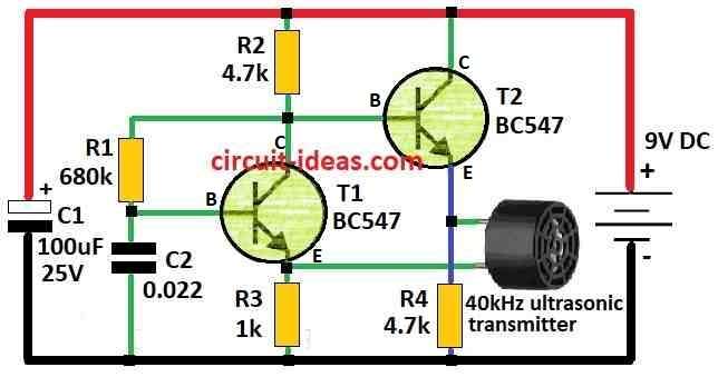
Circuit Working of Ultrasonic Transmitter:
Parts List:
| Components | Values | Quantity |
|---|---|---|
| Resistors | 680k | 1 |
| 1k | 1 | |
| 4.7k | 2 | |
| Capacitors | Ceramic 0.022µF | 1 |
| Electrolytic 100µF 25V | 1 | |
| Semiconductors | Transistor BC547 | 2 |
| Ultrasonic Transmitter 40kHz | 1 | |
| Battery 9V | 1 |
This circuit creates an ultrasonic sound that we cannot hear, so as to make a sound wall at the entrance; if someone break this sound wall a circuit hears that and make loud alarm sound which indicates someone has come inside.
Furthermore, this system can protect doors or areas from unauthorized people and the circuit has two main parts: one sound sender (transmitter) and one sound listener (receiver).
Also, both parts use same type of ultrasonic sender TX and receiver RX working at 40kHz sound.
Transmitter part use TX and two transistors T1 and T2 both are BC547 to make sound using special circuit called emitter coupled oscillator.
The resistor and capacitor values control how fast it make sound which must be 40kHz same like TX.
Formula:
In two transistor feedback oscillator circuit we have used positive feedback to keep the oscillation going, so we can use this easy formula to find the oscillation frequency (f):
f = 1 / 2π√(C * R)
where,
- C is capacitor value in feedback part.
- R is resistor value in feedback part.
Note:
This formula helps to know how many times the circuit oscillate in one second and by changing C and R values we can change the frequency.
So this circuit can work in different frequencies if we adjust the parts.
How to Build:
To build a Ultrasonic Transmitter circuit following are the steps to follow:
Transmitter Part:
- First, connect ultrasonic sender TX to oscillator circuit using two transistors T1 and T2 and use resistor and capacitor to be sure it work at 40 kHz.
Receiver Part:
- Next, connect the ultrasonic receiver RX to a circuit that can detect when the signal breaks and we can also use a simple comparator circuit for this purpose.
Alarm Part:
- Then connect alarm like buzzer to receiver part and when signal breaks, buzzer makes sound.
Note:
- Be careful while working with electronics and also be sure one knows what to do and stay safe.
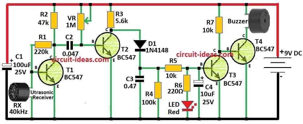
Circuit Working of Ultrasonic Receiver:
Parts List:
| Components | Values | Quantity |
|---|---|---|
| Resistors (All resistors are 1/4 watt unless specified) | 220k | 1 |
| 47k | 1 | |
| 5.6k | 1 | |
| 100k | 1 | |
| 220Ω | 1 | |
| 10k | 2 | |
| Preset 1MΩ | 1 | |
| Capacitors | Ceramic 0.047µF | 1 |
| Ceramic 0.47µF | 1 | |
| Electrolytic 100µF 25V | 1 | |
| Electrolytic 10µF 25V | 1 | |
| Semiconductors | Transistors BC547 | 4 |
| Diode 1N4148 | 1 | |
| LED Red 5mm 20mA | 1 | |
| Buzzer | 1 | |
| Ultrasonic Receiver 40kHz | 1 | |
| Battery 9V | 1 |
Receiver Part:
This part has a 40 kHz ultrasonic receiver RX connected to the base of transistor T1 and T1 works as an amplifier that strengthens the weak signal from the RX sensor.
Also, the strong signal from collector of T1 goes through capacitor C2 to next part with T2, diode D1 and capacitor C3.
When RX keep getting ultrasonic sound from TX, T3 stays ON (saturated) and keep working and because of this T4 stay OFF, since its base is at ground.
But when something blocks the ultrasonic sound RX stop receiving and then T3 turn OFF and T4 start to work.
Now buzzer connected to T4 collector makes sound with an alarm and a red LED stay ON in standby mode this means system is working and ready.
Range of Circuit:
This circuit works good for few meters only, but we must keep TX and RX facing each other on both sides of entry, if RX always get signal from TX then alarm stays OFF.
Formula:
Transistors in ultrasonic sensor amplifier circuits make the weak signal from the sensor stronger and the sensor can use a TX and RX ultrasonic pair.
Here, is simple formula for gain (Av) of transistor amplifier for ultrasonic signal:
Av = RC / re
where,
- RC is collector resistor
- re is small resistance inside emitter of transistor
We find re like this:
re = VT / IE
where,
- VT is thermal voltage about 26 mV at room temperature
- IE is emitter current
Note:
Hence, this formula help to build transistor amplifier for ultrasonic sensor and exact design depends on what ones need like how strong the signal must be and what frequency it works on.
How to Build:
To build a Ultrasonic Receiver Circuit following are the below mentioned steps:
Connect RX to T1:
- First, connect 40kHz ultrasonic receiver RX to base of transistor T1.
T1 as Amplifier:
- Set T1 as common emitter amplifier to make weak signal from RX stronger and then use proper resistors to give correct bias to base of T1.
Signal Detection Part:
- Connect the amplified signal from the collector of T1 to the next stage (T2, diode D1 and capacitor C3) and also ensure we connect and bias all parts correctly
Alarm Triggering:
- After that, use transistor T3 to control alarm.
- When RX always get signal from TX, T3 stay ON (saturated) and it keep T4 ON too, this keeps alarm OFF.
- If something block the ultrasonic signal RX stop receiving and then T3 turn OFF and T4 turn ON, also T4 make piezo buzzer sound like an alarm.
Standby LED:
- Connect red LED to show system is working with standby mode, for that use resistor with LED to control current.
Power Supply:
- Give power using good power source like battery or DC power that match circuit voltage.
Note:
- Ground all parts properly and keep the parts separate to prevent noise and false alarms.
- Also, change part values or wire layout if needed for better working.
Conclusion:
Overall, Ultrasonic Security Alarm Circuit is good and trusted way to find movement and sound alarm in protected area, as it uses ultrasonic sound wave to find if someone come inside without any permission.
Lastly, this system is good for home and factory security.
Leave a Reply