This article for Simple Triac Flasher Circuit show how to make one circuit to turn lightbulb ON and OFF, also, we can use one knob to change how fast light blinks from maybe two to ten times in one second.
Moreover, this simple and easy-to-make circuit suits beginners, but beginners should always follow safety precautions while handling electrical items.
What is a Triac Flasher Circuit:
Triac flasher circuit is one electric circuit which makes light like bulb blink again and again, also main part is Triac which is one semiconductor thing that controls AC current flow.
Mostly, people use this circuit for signal light decoration light and other places where we need light flashing many time.
Circuit Working:
Parts List:
| Components | Values | Quantity |
|---|---|---|
| Resistors | 6.8k 1/4 watt | 1 |
| Potentiometer 100k | 1 | |
| Preset 1k | 1 | |
| Capacitor | Electrolytic 220uF 100V | 1 |
| Semiconductors | Triac BT136 | 1 |
| Diac BD3 | 1 | |
| Diode 1N4004 or 1N4007 | 1 | |
| Bulb 40 watt | 1 |
To begin with, after AC power goes through 1N4004 diode it changes to DC and this DC signal goes to RC part with one capacitor and resistor.
First, there is a big capacitor of electrolytic 220uF when it is full charge it make diac DB3 break and pass voltage, then capacitor gives current through diac and triac to turn ON.
Also, the bulb flashes because triac is ON and make one bright light then it goes OFF and after light there is wait time and this time it is control by 100k potentiometer.
Now, this time capacitor charges again slowly until near diac level bulb blink again and this happens again and again and discharge, fire triac, light ON, wait, charge, so bulb keep flashing same speed as setting.
Here, the circuit uses a 1k resistor and this resistor decides how much current the triac needs to turn ON, it also helps the circuit work properly.
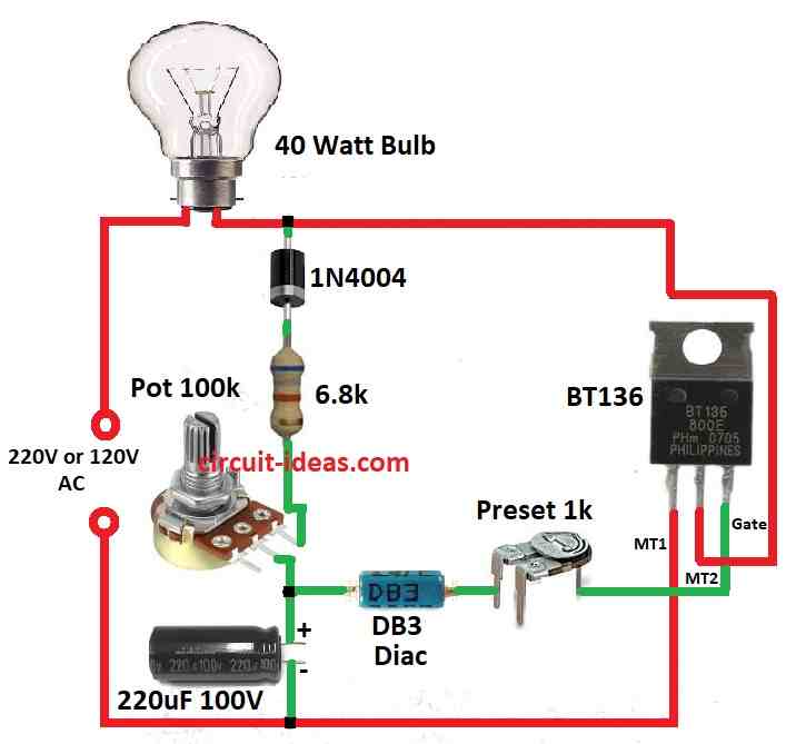
Wiring detail:
Here, MT1 of triac BT136 connect to AC phase and also to 40W bulb in line and MT2 of triac goes to AC neutral.
One 1N4004 diode and 6.8k resistor connect AC phase to 100k potentiometer and one 220uF capacitor connect other end of potentiometer to AC neutral.
Also, diac connect between middle of potentiometer and capacitor and other end of diac connect to triac gate using 1k preset.
Adjusting flash:
Main control to change flash speed is 100k potentiometer and 1k preset help adjust flashing more fine and proper.
Formulas and Calculations:
This circuit uses charging and discharging time of capacitor C1 to control when triac BT136 turn ON and OFF.
Time Constant (τ):
Also, one important thing for flash speed is time constant which tells how fast capacitor charges or discharges.
Time constant (τ) = R × C
where,
- R is resistance
- C is capacitance.
It mean how long capacitor take to reach about 63% voltage.
In this circuit:
R = R1 = 100k ohm
C = C1 = 220µF
So,
τ = R × C = 100,000 × 220 × 10⁻⁶ = 22 seconds
Finally, 22 seconds is time for one charging or discharging.
How to Build:
To build a Simple Triac Flasher Circuit follow the below steps for connections:
- First, connect MT1 pin of triac BT136 to AC phase which is the live wire and connect MT2 pin to AC neutral.
- Now from AC phase use 1N4004 diode and 6.8k resistor to connect to one side of 100k potentiometer.
- Then connect other side of potentiometer to neutral using 220µF capacitor.
- Also, join one side of diac to middle point between potentiometer and capacitor.
- After that, other side of diac goes to triac gate using 1k preset resistor.
- Next, put 40W bulb in series with MT1 of triac and other side of bulb connect to neutral wire.
- Now connect whole circuit to main power AC with right polarity and safety.
- Use 100k potentiometer to change flash speed of bulb and ise 1k preset resistor to fine adjust flashing rate.
- After that always remember to switch OFF power before touching or fixing anything and also double check all wire connections.
- Lastly, use tools with insulation with no bare metal and if confused or not sure ask someone who knows electronics.
Conclusion:
To conclude, in this Simple Triac Flasher Circuit working with main electricity is not safe if done wrong.
So better to ask help if something is not clear and also safety is more important than anything.
Leave a Reply