Simple Day Night Activated Switch Circuit using a Triac and LDR show how to make circuit which turns ON and OFF things by seeing outside light; also we only need one light sensor (LDR), one resistor, one capacitor and one special switch called Triac.
Moreover, many alarm systems use this circuit because it turns ON the light at night and turns OFF in day automatically.
Also, the circuit does not need extra motor or switch, and it works with normal home electricity.
WARNING: Be careful working with high voltage can be dangerous, so do it with adult or someone who know how to do electric work safe.
Circuit Working:
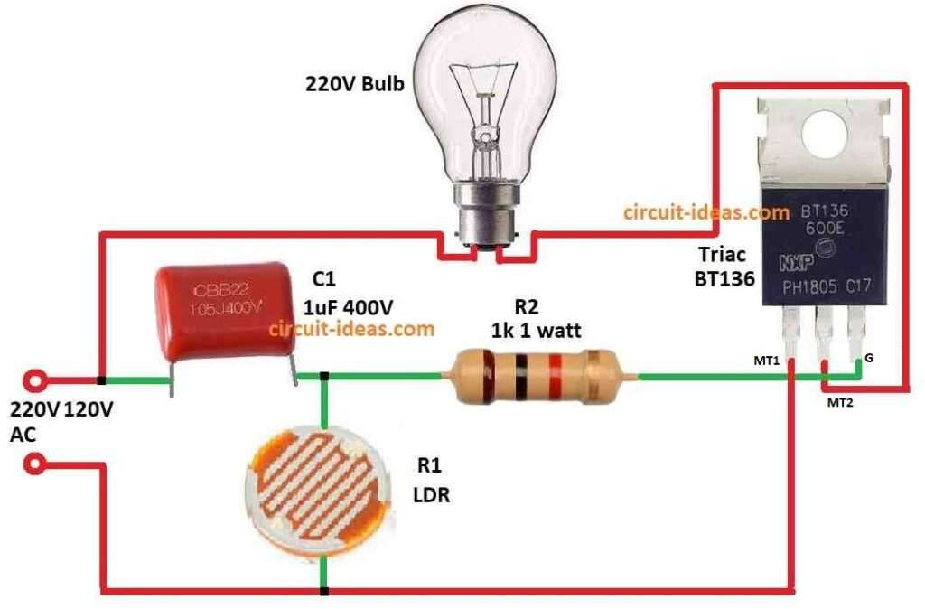
Parts List:
| Components | Values | Quantity |
|---|---|---|
| Resistor | 1k 1 watt | 1 |
| LDR | 1 | |
| Capacitor | PPC 1uF 400V | 1 |
| Semiconductors | Triac BT136 | 1 |
| Bulb 220V | 1 |
To begin with, this day night switch circuit uses triac and LDR, it is very simple and cheap to make and is easy also; but one problem it is strong (solid) and does not allow to change or control electronic way.
Also, this circuit does not use a normal switch because it uses Triac or SCR instead of mechanical switch.
Many circuits already turn ON lights when darkness comes, but normally those circuits use electromechanical relay and DC power.
But this one connect direct to AC power so less parts needed.
Here, LDR is very important in this circuit because it change resistance by light; in Quebec at night it show around 200 ohm and in day few thousand ohm, it depend how much light comes.
Furthermore, LDR and Triac gate get power from capacitor C1 and this work like voltage divider and when light is normal voltage goes down because LDR resistance goes down.
Hence, at night LDR resistance goes up so Triac get more current and turns ON light.
Formulas:
To make Day Night Switch we can build circuit that turn ON or OFF 220V bulb depending how much light LDR sees; also the circuit uses special formula for connecting parts.
We can find voltage across LDR (VLDR) like this:
VLDR = Vsupply × RLDR / (RLDR + Rfixed)
where:
- Vsupply show power given to LDR and resistor.
- RLDR is resistance of LDR which changes with light.
- Rfixed is normal resistor and in this circuit it is 1k ohm.
Capacitor Working:
The 1µF capacitor C help to smooth or control voltage and this capacitor charge in time is like this formula:
R × C = t
where:
- It shows charging time which is called the time constant.
- R is resistance in same line with capacitor
- C is value of capacitor.
How fast this happen depend on how much light LDR sees.
How to Build:
To build a Simple Day Night Activated Switch Circuit using a Triac and LDR follow the below mentioned steps for connections:
Triac Connection:
- First, connect triacs MT1 and MT2 to AC mains power.
Resistor and LDR:
- Next, connect MT1 of triac to one leg of LDR and connect one end of resistor to other leg of LDR and then connect resistors other end to triac gate.
Capacitor Connection:
- After that, connect one leg of capacitor C1 to where LDR and resistor meet and connect other leg of capacitor to MT2 of triac.
Diac Connection:
- Then one leg of diac connect to triac gate and other leg of diac join at point where LDR, resistor and capacitor meet.
- To show ON/OFF, connect LED between MT1 and MT2 of triac.
Power Source:
- Also, connect full circuit to AC mains power.
Key Points:
- After that, check all wires and parts are safe with no short circuit and be careful while working with AC mains power.
- Also, choose correct parts and check datasheets before using.
Conclusion:
Overall, in Simple Day Night Activated Switch Circuit using a Triac and LDR, the circuit turns OFF the light in day and turns ON the light at night by itself after all connections complete.
As a result, we can change resistor value or try different LDR to match light level in our place; for that better to check datasheet or ask someone who knows electronics.

Leave a Reply