This tutorial show how to make a Flashlight Activated Remote Control Circuit.
We can turn it ON using flashlight.
It uses light sensor and this sensor is made with one transistor and special LDR that sees flashlight.
This article tell step-by-step guide how to build flashlight remote circuit and how to use it.
What is a Flashlight Activated Remote Control:
We can use flashlight or other light to control electric device with this flashlight remote control.
This idea work because some device use light sensor or photodiode to see light change.
When we point flashlight to sensor the remote control do things like turn ON TV, stereo or other devices.
Circuit Working:
Parts List:
| Component Type | Component Details | Quantity |
|---|---|---|
| Resistors | 10k 1/4 W CFR | 3 |
| 56k 1/4 W CFR | 1 | |
| 2.2M 1/4 W CFR | 1 | |
| Capacitors | Ceramic 0.22µF | 1 |
| Electrolytic 1µF 25V | 2 | |
| Semiconductors | Transistor BC547 | 1 |
| Transistor BC557 | 1 | |
| Diode 1N4148 | 6 | |
| IC 4017 | 1 | |
| LDR (Light Dependent Resistor) | 1 | |
| Relay 12V | 1 |
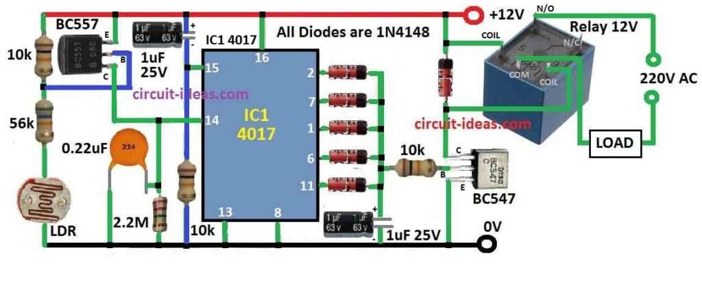
Main part of this circuit is Transistor BC557 which works like light sensor with LDR and other small parts.
LDR is put between negative wire and transistor base.
When light hit LDR it gives signal to BC557 base and BC557 start working.
When BC557 conduct IC1 pin 14 get high signal and this changes the state of IC.
Because of this change relay turn ON or OFF and the connected device also turn ON or OFF.
This ON/OFF stay like this until flashlight again shine on LDR.
LDR is inside black pipe to about 1 inch long which helps it to work good.
This way is normal room light not does not go inside pipe and disturb LDR.
We must keep pipe in angle so flashlight beam can go easily on LDR.
Formula:
Below is formula for Flashlight Remote Control Circuit:
Circuit work = Transistor T3 + LDR + other parts
BC557 start working = Light fall on LDR
Pin 14 of IC1 change = Relay turn ON or OFF
Toggle action = Load connects ON and OFF again and again
How to Build:
For building a Flashlight Activated Remote Control Circuit follow the below mentioned steps:
- First make PCB ready and give proper power supply.
- Connect LDR between negative wire and base of BC557 transistor.
- Be sure BC557 get correct bias from LDR.
- When we connect IC1 check all pins connect to right place.
- Connect T3 transistor collector to IC1 pin 14.
- To make relay ON/OFF connect it to IC1 output.
- Check if relay can handle the load we want to control.
- Put LDR inside black pipe which is around 1 inch long.
- Keep pipe in angle so flashlight beam can hit LDR easily.
- To stop wrong light from triggering circuit put 0.22µF capacitor in circuit.
- Now connect power supply to the circuit.
- Be sure voltage is OK for all parts.
Testing with flashlight:
- Shine flashlight on LDR to test.
- See if relay goes ON and OFF with light.
Adjustments:
- If needed change angle and position of black pipe for better light focus.
Final step:
- When everything work good build circuit on proper board or PCB for final setup.
- Check all parts and resistor values carefully.
- Use right datasheet for each part.
- Always be safe when working with electronics.
Conclusion:
By following these steps and adding needed parts we can make correct Flashlight Activated Remote Control Circuit
It can be controlled carefully using flashlight or other light.
Leave a Reply