This 220V Lamp Flasher Circuit using IC 555 uses one special chip IC 555 to make normal bulb blink like party light, also the chip make ON/OFF signal.
Furthermore, this signal connects to transistor or triac which work like switch for bulb power and when power goes ON and OFF fast then bulb start blinking in fixed speed.
But be careful this circuit uses 220V power which is very dangerous and we must take safety while making this circuit, so better contact a person who know electronics and who deals with high voltage to do this project.
Circuit Working:
Parts List:
| Components | Values | Quantity |
|---|---|---|
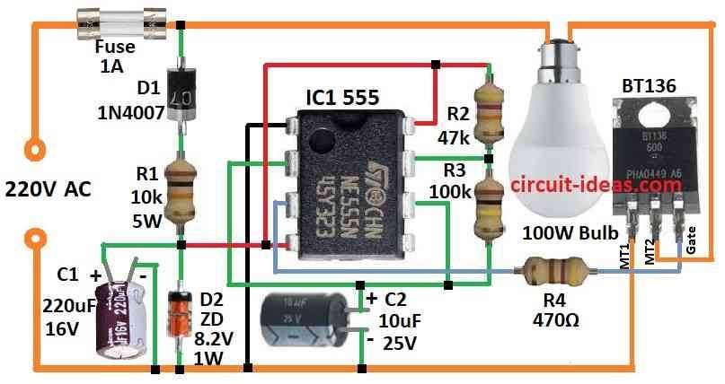
| Resistors | 10k 5W | 1 |
| 47k 1/4 watt | 1 | |
| 100k 1/4 watt | 1 | |
| 470Ω 1/4 watt | 1 | |
| Capacitors | Electrolytic 220µF 16V | 1 |
| 1Electrolytic 0µF 25V | 1 | |
| Semiconductors | IC 555 | 1 |
| Triac BT136 | 1 | |
| Zener diode 1W 8.2V | 1 | |
| Diode 1N4007 | 1 | |
| 100W Led bulb | 1 | |
| Fuse 1A | 1 |
To begin with, this circuit makes lamp blink and work with 220V power; it use 555 IC to control ON and OFF time of triac and this triac control power to lamp.
Power for IC come from half wave rectifier D1 and voltage control parts D2 and R1 and filter capacitor C1.
Lamp stay ON for around 1 second then goes OFF for 0.7 second and we can change ON and OFF time by changing R2 and R3 values.
Formulas:
This circuit use triac to safely control 220V AC bulb with help of 555 IC, also triac and other parts work like middleman they keep high voltage AC and low voltage 555 IC part separate and safe.
Hence, it is very important to know how to calculate frequency and duty cycle of 555 IC when it work in astable mode.
Frequency:
f = 1.44 / ((R1 + 2 × R2) × C)
Duty Cycle:
Duty Cycle = (R1 + R2) / (R1 + 2 × R2)
where:
- f is frequency in hertz Hz
- R1 and R2 are resistors in ohms
- C is capacitor in farads
We can use this formula to find duty cycle and design the blinking timing of the bulb.
How to Build:
To build a 220V Lamp Flasher Circuit using IC 555 we need to follow the below mentioned steps:
- First, connect 555 IC in astable mode and then join pin 2 and pin 6 together and connect this to point between R1 and D2.
- Next, connect pin 4 and pin 8 both to positive side of power.
- Then connect pin 1 ground to negative side of power.
- After that, connect pin 3 output to triac gate using resistor R4.
- Now take one wire of lamp or LED and connect to one side of AC mains and connect the other wire of lamp to triac load terminal and also connect other AC mains wire to main terminal of triac.
Note:
- This circuit uses high voltage of 220V so be very careful; use good insulation and safety tools while working with mains power.
Conclusion:
To conclude, We can make 220V Lamp Flasher Circuit using IC 555 this will blink lamp or LED that connect to 220V mains power.
Here, 555 IC work in astable mode to make square wave signal and this signal control switch part which turn lamp ON and OFF to make flashing.
Therefore, if we change timing parts like resistors and capacitor we can change how fast the lamp flashes.
Leave a Reply