In this post for How to Build a Mini Tesla Coil Circuit these tesla coil make high voltage and low current.
Furthermore, mini tesla coil is small version of big one and it can light small things or make tiny sparks and also it runs on 9V battery or other low power.
Circuit Working:
Parts List:
| Components | Values | Quantity |
|---|---|---|
| Resistor | 22k 1/4 watt | 1 |
| Semiconductors | Transistor 2N2222 | 1 |
| Red LED 5mm 20mA | 1 | |
| ON/OFF Switch | 1 | |
| Coil on super enameled copper wire primary winding 6 turns, secondary 275 turns | 1 | |
| Battery 9V | 1 |
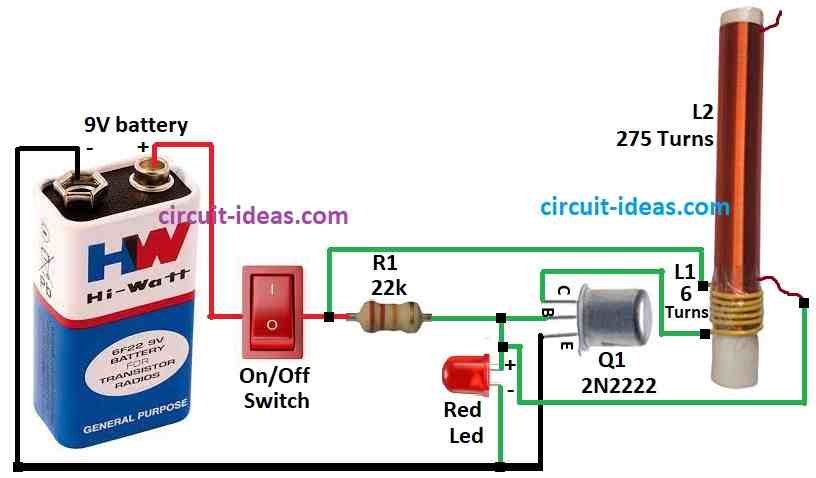
To begin with, this small Tesla coil circuit have two parts switch part and coil step-up part.
L1 coil connect to Q1 transistor 2N2222 at collector pin and it act like switch and also L1 make magnetic flux when power goes in.
Moreover, winding setup is very important, we need to do winding first before starting the full circuit and we should have 3 inch and half feet PVC pipe (size can change).
Use insulated wire for primary coil and also need non-conductive round material.
First, make the secondary coil using 22 SWG copper wire and wind 275 turns on a PVC pipe and connect one end of this coil to the transistor base and leave the other end open and then, make the primary coil with 6 turns.
Battery power goes to Q1 transistor base and coil through switch and then put resistor R1 to base pin; also we can add red LED from negative supply to base to see pulse.
Battery negative connect to emitter, L1 coil goes to collector and base also connect to L2 coil.
When power is ON, Q1 stay OFF at start, but base get little power so Q1 slowly turn ON and then full power goes to L1 coil and then L1 make magnetic field.
Also, because L2 have more turns it also make magnetic flux and gives high voltage and this loop goes on while power is ON, then L2 flux send more power to base and make Q1 more ON.
But then base power drop because battery power flow decreases and Q1 reach saturation means with fully ON.
Formulas:
To make Tesla coil we need some formulas and electric knowledge.
Main formulas:
1. Primary coil frequency (f):
f = 1 / (2π√LCp)
where,
- Cp is the main capacitor value
- L is the primary coil inductance
2. Secondary coil frequency (f):
f = 1 / (2π√Ls(Cs + Ct))
where,
- Ls is the secondary coil inductance
- Cs is the coil self capacitance
- Ct is the top capacitance from top terminal
3. Coil inductance (L):
L = (N² * μ0 * A) / l
where,
- N is the number of turns
- μ0 is 4π × 10⁻⁷ H/m for constant
- A is coil area for cross-section
- l is the coil length
These formulas help to build Tesla coil, but we also need to think about safety, insulation and what materials we need to use.
How to Build:
How to Build a Mini Tesla Coil Circuit follow the below mentioned steps:
- First, take parts as shown in circuit diagram.
- Next, connect Q1 transistor collector to L1 coil of primary winding.
- After that, connect Q1 base to 9V battery positive using resistor R1 and ON/OFF switch, connect Q1 emitter to ground and connect red LED from Q1 base to ground.
- Then put L1 coil between R1 resistor and ON/OFF switch and connect L2 coil of secondary winding is between Q1 base and red LED.
- Now connect 9V battery positive to ON/OFF switch and connect 9V battery negative to ground.
Safety Notes:
- Even small Tesla coil make high voltage, but we need to be careful, do not touch coils when ON and keep away from kids and pets.
Conclusion:
To conclude, How to Build a Mini Tesla Coil Circuit is fun for science lovers; but always follow safety rules and stay away from coils when power is ON.
Leave a Reply