No more boring ding dong bell!
This Touch Controlled Musical Door Bell Circuit show how to make doorbell which play small music tune; just press a button and it rings a melody sound which we can choose which one.
Also, this circuit is fun idea to make door more special and different.
Circuit Working:
Parts List:
| Components | Quantity |
|---|---|
| Resistors | |
| 100k 1/4 watt | 2 |
| Capacitor | |
| Ceramic 47pF | 1 |
| Semiconductors | |
| Transistors BC547 | 2 |
| IC UM3481 | 1 |
| Diode 1N4007 | 1 |
| Speaker 8Ω | 1 |
| Battery 3V | 1 |
| Touch Pad (metal plate) | 1 |
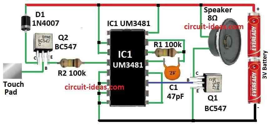
To begin with, this circuit uses touch control to play music bell when someone touches the touch pad, also it makes enough sound with only two AA battery.
Furthermore, the circuit uses popular IC UM3481 and this IC already have many parts inside like oscillator, frequency divider, modulator, control system, ROM with 512 music notes and preamplifier.
Also, this circuit needs only few extra parts to make full circuit.
Here, C1 and R1 set the oscillator timing inside the IC, Q1 powers the speaker and the base of Q2 acts as a touch pad to start the music bell.
Formula:
We can make touch music bell using UM3481 IC, one touch pad and some small parts and for touch control we can use special touch module or simple RC circuit.
Touch timing formula is:
τ = R × C
R is resistor and C is capacitor.
Timing Setup:
To ensure touch work good with UM3481 and change R and C values as needed and with UM3481 IC and these simple steps we can make nice touch music bell.
Hence, check the datasheet to see IC pins and which melody it can play and change circuit or parts if we need different tune or setup for our project.
How To Build:
To build the Touch Controlled Musical Door Bell Circuit we need to follow the below mentioned steps:
Check Components:
- First, check all parts in circuit diagram are there.
Place IC UM3481:
- After that, put IC UM3481 on breadboard or PCB and ensure it sits right.
Power Connection:
- Then connect AA battery to positive side to Vcc pin of IC and negative side to ground pin.
Timing Parts:
- After that, connect resistor R1 and capacitor C1 to right IC pins as these are for timing and check UM3481 datasheet for which pins to use.
Speaker Connection:
- Next, connect one wire of speaker to collector of Q1 and other wire of speaker goes to positive power side and connect emitter of Q1 to ground.
Transistor Connection:
- Now connect base of Q1 to IC pin that give sound signal and also connect base of Q2 to touch pad.
Final Check:
- Finally, check all wire again and ensure nothing is loose or short.
Test Circuit:
- First, put AA batteries in holder and now touch the pad and the music will start playing.
- Also, if no sound or not sensitive then change R or C value at Q2 base to adjust.
Be Careful:
- Always be careful with circuit and check wire and polarity before power ON and also a wrong wire can break parts.
Conclusion:
To conclude, this Touch Controlled Musical Door Bell Circuit is better than old-style doorbell, as we can change the melody and make doorbell with more fun.
Moreover, it is good for home or office entrance.
Leave a Reply