This post is about a Simple Ticking Bomb Simulator Circuit, which make ticking sound like real bomb in movie or game.
Also, this circuit is just for fun and with no real danger.
Circuit Working:
Parts List:
| Components | Values | Quantity |
|---|---|---|
| Resistor | 47k 1/4 watt | 1 |
| Capacitors | Electrolytic 10μF 25V | 2 |
| Semiconductors | IC 555 | 1 |
| Speaker 8Ω | 1 |
To begin with, we can make ticking sound like bomb using this simple ticking bomb simulator circuit.
How circuit work:
Circuit uses 555 timer IC which is very good for timer jobs and this circuit work as astable multivibrator and it makes signal go ON and OFF again and again.
Also, capacitor C1 with 10uF and resistor R1 with 47k control the timing and these parts decide how fast ticking sound comes.
Furthermore, we can change R1 or C1 to make ticking faster or slower, also C1 also help control how much current goes to speaker and finally, speaker make ticking sound and follow signal from 555 timer IC.
Formulas:
Using 555 IC in astable mode we can make ticking bomb simulator, it gives ticking sound like countdown timer by making repeated pulse.
Important Formula:
Frequency (f):
f = 1.44 / (R1 + 2×R2) × C
- R1 and R2 are the resistors with 555 IC
- C is the capacitor with 555 IC
This formula say how fast the ticking sound comes.
Duty Cycle D:
D = (R1 + R2) / (R1 + 2×R2)
This show how much time signal stay high in one cycle, so we use these formula to control sound speed like ticking clock or bomb.
The pulses goes to speaker and make sound and as a result, we can change parts to make sound faster or slower for better simulation.
How to Build:
To build a Simple Ticking Bomb Simulator Circuit we need to follow the below mentioned connections process:
- First, put all parts like in the circuit diagram.
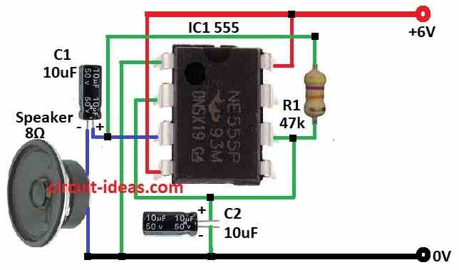
- Then connect pin 1 of IC 555 to ground.
- Next, connect pins 2 and 6 together.
- Now pin 3 goes to ground through 8 ohm speaker and capacitor C1.
- Pin 4 connect to +6V power and pin 8 also connect to +6V power.
- After that, pin 6 connect to one side of resistor R1 and other side goes to pin 3.
Safety Tips:
- This circuit is safe but still be careful with electronics, use only power that match circuit with 6V.
- Never plug it into wall socket which is the mains power, as risk of shock is low but always stay careful.
- Do not make it if anyone do not not feel safe with electronics.
Conclusion:
Overall, this Simple Ticking Bomb Simulator Circuit makes fun ticking sound not real bomb, as it use 555 timer to make repeat signal.
Furthermore, we can change tick speed with parts like resistor and capacitor.
Leave a Reply