This is Simple Metal Detector Circuit using IC 555, uses IC 555 chip which works like small clock and makes signal to help find metal and magnet
Also, it is easy to build and good for beginners.
Circuit Working:
Parts List:
| Components | Values | Quantity |
|---|---|---|
| Resistor | 47k 1/4 watt | 1 |
| Capacitors | Electrolytic 10μF 25V | 1 |
| Electrolytic 2.2μF 25V | 2 | |
| Semiconductors | IC 555 | 1 |
| Coil 10mH | 1 | |
| Speaker 8Ω | 1 |
This article show how simple metal detector work using IC 555, as it makes magnetic field that keep changing means oscillating.
Also, when metal comes near the coil it break magnetic field and changes the frequency and then speaker hear this change and makes sound.
How circuit work:
IC 555 work as astable multivibrator and give square wave at pin 3.
Resistor R1 and capacitor C1 set the frequency and then C1 and R1 together control how fast wave come means oscillation.
Then, the speaker produces a sound when the frequency changes, as shown in the circuit diagram
Furthermore, capacitor C2 stop noise and help circuit work better.
After that, we wrap a wire around a form to create a coil and when current flows through the coil, it generates a magnetic field; furthermore, the coils size and the number of wire turns show the operating frequency.
Hence, when metal come close frequency changes and speaker sound get higher.
Formulas:
IC 555 in astable mode can make metal detector, it creates changing oscillating the electromagnetic field.
When metal comes near the detector, it changes the frequency of the electromagnetic field and as a result, the detector identifies the presence of the metal.
The following formula helps calculate the values for this circuit:
Frequency (f) formula:
f = 1.44 / (R1 + 2×R2) × C
where:
- R1 and R2 are the resistors in circuit
- C is the capacitor in circuit
This formula help to find and change frequency of IC 555 and by changing R1, R2, C and coil we can make detector more sensitive and better at finding metal.
How to Build:
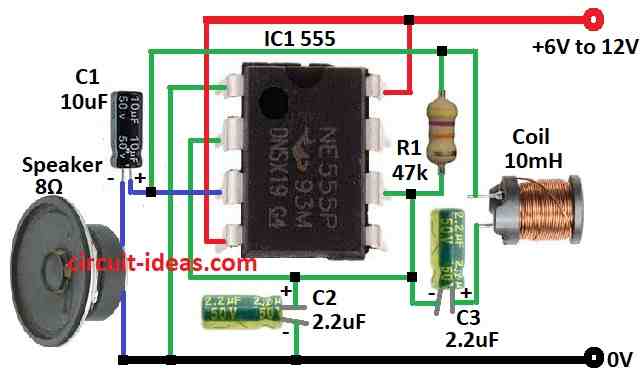
To build a Simple Metal Detector Circuit using IC 555 below mentioned are the steps for connections:
- First, take all parts as shown in diagram.
- Next, connect pin 1 of IC 555 to ground.
- Then connect pin 2 to pin 6 and also connect capacitor C2 from pin 2 to ground.
- After that, connect pin 3 to ground using capacitor C1 and 8 ohm speaker.
- Now connect pin 4 to +6V to +12V supply and also connect pin 8 to +6V to +12V supply.
- Connect pin 6 to one side of resistor R1 and other side to + supply.
- Also, connect coil 10mH and capacitor C3 between pin 2 and pin 6.
Extra Note:
- Circuit can act different if ground is not good.
- We may need to change R1 to make it work better and bigger C1 or coil is more sensitive but also more noise.
Conclusion:
To conclude, Simple Metal Detector Circuit using IC 555 makes signal that change when metal is near, as it help detect metal but cannot say which metal it is.
Therefore, this circuit is good for basic understanding.
Leave a Reply