This Thunder Lightning Detector Circuit teaches us how to make lightning detector, a tool used by storm chasers!
Moreover, lightning makes special energy in sky and when storm come, this circuit find that energy and give alert by light or sound; so person can go safe place before rain start.
Circuit Working:
Parts List:
| Components | Values | Quantity |
|---|---|---|
| Resistors (All resistors are 1/4 watt unless specified) | 10M | 1 |
| 330k | 1 | |
| 100k | 1 | |
| 15k | 1 | |
| 33k | 1 | |
| Preset 10k | 1 | |
| Capacitors | Ceramic 100pF | 1 |
| Ceramic 470pF | 1 | |
| Ceramic 10nF | 1 | |
| Ceramic 4.7nF | 1 | |
| Electrolytic 47μF | 2 | |
| Semiconductors | Transistor BC547 | 3 |
| Diode 1N4148 | 1 | |
| LED 20mA 5mm | 1 | |
| Piezo Buzzer | 1 | |
| Antenna 150mm (6 inch wire) | 1 |
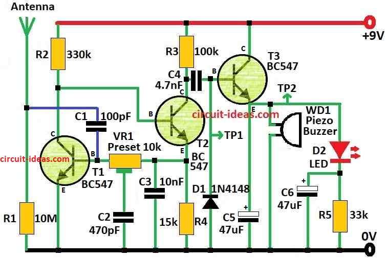
To begin with, when the circuit find lightning it discharge and it makes LED blink or buzzer sound alarm and this help people take action early before storm come.
With resistor values shown in circuit diagram the detector adjust itself to work in best relaxing way and this is the main feature.
DC oscillator send signal back to T2 base from T1 collector and VR1 preset control how strong the whole loop works.
Watch test point TP1 and adjust VR1 until it start to oscillate and try to get around 7V peak-to-peak, this mean lightning sensor is ready.
Furthermore, at TP2 we should see +6V DC and to stop oscillation slowly adjust VR1 and touch aerial side of C1 with screwdriver.
After 1 to 2 seconds alarm will turn OFF and this will make small changes and see if it stays stable.
We can also rub plastic ruler to make static and then bring it near aerial to about 2 meters away where circuit should detect it.
Also, in standby mode circuit uses only around 600µA and run from 9V battery and if keep powered always, then it can work for full year.
When alarm turns ON it uses more power to about 4mA, for that thanks to low power sounder WD1.
Hence, for good working power should not go below 3V as it gives fast “ping” sound when any static pulse is near.
Formulas:
To be sure circuit work good and all parts value are correct in thunder lightning detector we can use some easy formulas and how to use them are shown below:
Base Resistor Formula:
A base resistor (RB) helps the transistor stay active and receive the correct current.
RB = (VCC − VBE) / IB
- VCC is power supply with 9V in this circuit
- VBE is voltage from base to emitter for BC547 it is 0.7V
- IB is base current
To get IB:
IB = IC / hFE
- IC is collector current
- hFE is gain of transistor for BC547 usually 100
Timing and Filter Capacitor Formula:
For simple RC filter to find cutoff frequency:
fc = 1 / (2πRC)
- fc is cutoff frequency in Hz
- R is resistance in ohms
- C is capacitor value in farads
Resistor Power Dissipation:
To know how much heat resistor make:
P = I² × R
- P power lost watts
- I is current through resistor amps
- R is resistance in ohms
Capacitor Reactance Formula:
To check how capacitor block AC at different frequencies:
XC = 1 / (2πfC)
- XC is capacitor reactance in ohms
- f is signal frequency for Hz
- C is capacitance in farads
LED and Buzzer Power Formula:
To protect LED or buzzer from too much current:
I = (Vsupply − VLED) / RLED
- I is current in amps
- Vsupply is power source voltage
- VLED is LED forward voltage which is usually 2V
- RLED is resistor in series with LED in ohms
Hence, these formulas help to build and test lightning detector better, also change parts values if needed so circuit work as we want.
How to Build:
To build a Thunder Lightning Detector Circuit follow the below steps for connection of the circuit:
Collect the Parts:
- First, ensure all parts for circuit are ready before starting.
Build the Circuit Board:
- Next, put all parts on circuit board same like in the diagram and use wires to connect parts and then solder them in place.
Place Transistors T1 and T2:
- Now check we put transistors in right position, as T1 collector must go to T2 base.
Connect VR1 Preset:
- Then connect multiturn preset VR1 as shown in diagram.
Add Capacitor C1:
- After that, put capacitor C1 in circuit, with one side goes to base of transistor T1 and other side goes between antenna and resistor R1.
Connect Sounder WD1:
- Next, connect low current sounder WD1 in circuit and also be sure connection is correct so alarm can work well.
Connect Antenna:
- Now use short wire and connect it to the antenna point on board.
Give Power:
- Also, connect 9V battery to power the circuit.
- First, watch test points TP1 and TP2.
- Adjust preset VR1 until we see circuit start oscillating and voltages are okay.
- Test circuit by touching aerial side of C1 with metal or use static method like plastic ruler to stop oscillation and fine-tune if needed.
Final Adjustments:
- If anything is not working then make small changes to fix.
Important Note:
- Be careful while soldering and working with electric parts and if anyone is a beginner then ask help from someone with experience.
- Always check each step to avoid mistake or damage.
Conclusion:
To conclude, this Thunder Lightning Detector Circuit may not catch every strike but it can give warning when storm is coming.
Therefore, how good it works depends on antenna size, sensor sensitivity and outside weather conditions.

Leave a Reply