Simple Static Electricity Detector Circuit is like alarm for electricity when gathers on things like clothes and this happen when we rub things together.
Also, this kind of electricity can break small electronics, so detector is useful near them; also detector have special sensor which feels electric change in air.
Maybe its wire stick out or maybe flat plate, when it feel static it turns ON light or make sound and say “Hey! Electricity here!”
Circuit Working:
Parts List:
| Components | Values | Quantity |
|---|---|---|
| Resistors | 1M 1/4 watt | 2 |
| 470Ω 1/4 watt | 2 | |
| Capacitors | Electrolytic 100µF 25V | 1 |
| Semiconductors | JFET 2N3819 | 1 |
| Red LED 5mm 20mA | 1 | |
| Antenna 1m flexible wire | 1 | |
| Battery 9V | 1 |
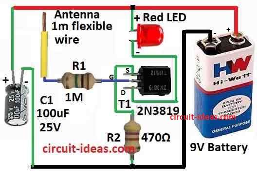
To begin with, in this article we have used JFET T1 2N3819 to catch static electric touch.
The connections of the circuit components are as follows::
First, the gate connect to 1 meter wire antenna with 1M resistor called R1 and source connects to ground using 470 ohm resistor called R2.
The circuit also includes an LED between the JFET drain and the positive terminal of the battery and a 9V battery powers the entire circuit.
When antenna feel static charge JFET make signal bigger and LED lights up to show it have caught something.
Formulas and Calculations:
We can make easy circuit using JFET 2N3819 to find static electricity but just use parts like mentioned in the diagram above and build static detector.
Main idea is simple JFET work like amplifier with high resistance and it catches very small voltage change from static and then LED light up to show static is there.
LED Current:
When the circuit detects static electricity, the LED receives current as follows:
ILED = VBattery−VLED / RLED
where,
- Battery is 9V
- LED drop is 2V
- Resistor is 470 ohm
Therefore:
ILED = 9V − 2V / 470Ω = 14.9mA
This current is enough to turn LED ON, as this simple static finder is good for many jobs for testing static, showing static in class and more.
Furthermore, it is easy to make but still works very well!
How to Build:
To build a Simple Static Electricity Detector Circuit we needs to follow the below mentioned assembling steps:
- First, take gate of JFET and connect it to one side of 1M resistor R1 and other side of that resistor connects to 1 meter long antenna.
- Now connect source pin of JFET to one side of 470 ohm resistor R2 and other side of R2 connects to ground.
- Then drain of JFET connect to positive leg anode of LED and negative leg cathode of LED connect to plus (+) side of 9V battery.
- Minus (−) side of battery connects to ground.
Note:
- Be sure all wires are tight and parts are in right place and when antenna feel static, JFET make signal strong and LED will turn ON to show it.
Conclusion:
Overall, this Simple Static Electricity Detector Circuit is useful tool; as it helps to find and show static charge which can hurt small electronic parts.
Moreover, by using sensor and making signal bigger this circuit help keep electronics safe from static shock and also it ensures they work good and last for long time.
Leave a Reply