Many electronic circuits require a DC power supply, while the mains provides AC power, also this Simple 12 V Power Supply Circuit with Filter Capacitor converts AC into 12V DC and delivers up to 2 A of output current.
This circuit uses only a few components, making it simple, low cost, and easy to build, it also serves as an excellent project for beginners and provides a suitable power supply for audio amplifiers.
Also, it is useful for electronics projects and is good for testing boards and lab work.
Circuit Working:
Parts List:
| Components | Values | Quantity |
|---|---|---|
| Resistor | 1.2k 1/4 watt | 1 |
| Capacitor | Electrolytic 2200uF 25V | 1 |
| Semiconductors | LED any color 5mm 20mA | 1 |
| Diode 1N5402 | 2 | |
| Fuse 1A | 1 | |
| ON / OFF Switch | 1 | |
| Transformer primary 220V AC, secondary 12V-0-12V 2A center Tap | 1 |
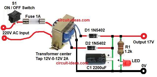
First, the circuit receives the AC supply, switch S1 then turns the circuit ON or OFF and fuse F1 protects the circuit by interrupting the power if excessive current flows through it.
Next, transformer steps down voltage and it converts 230V AC to 12V-0-12V AC.
Then diodes D1 and D2 act as rectifier and they convert AC voltage into pulsating DC and afterward the capacitor C1 filters the ripple and so the output becomes smooth DC.
Finally, LED shows power ON indication and the output DC voltage is around 17V without load.
Why output is 17V and not 12V?:
Because 12V is RMS value and after rectification the peak voltage increases, also, capacitor charges to peak value and therefore output becomes higher than 12V.
Formula with Calculation:
RMS voltage of transformer secondary = 12V
Formula for peak voltage is:
Peak voltage = RMS voltage x 1.414
Peak voltage = 12 x 1.414
Peak voltage = 16.97V
This means AC voltage goes up to 16.97V at its highest point and therefore, after rectifier and capacitor voltage becomes near 16.97V value.
How to Build:
To build a Simple 12V Power Supply Circuit with Filter Capacitor follow below steps for connection:
- Start, the circuit connection by collecting all the circuit parts as shown in above diagram.
- Then start with transformer primary pins and connect to AC mains via switch and fuse.
- Next, secondary pins connected to 12V, CT and 12V and center tap pin connects to ground line.
- Now diode D1 1N5402 anode connects to one 12V pin of transformer and cathode connects to positive output.
- After that, diode D2 1N5402 anode connects to another 12V pin of transformer and cathode connects to positive output and positive of capacitor C1.
- Also, capacitor C1 positive pin connects to positive output and negative pin connects to ground.
- Finally, LED anode connects to resistor R1 and cathode connects to ground and resistor R1 one side connects to positive output and other side connects to LED anode.
Conclusion:
To conclude, this Simple 12V Power Supply Circuit with Filter Capacitor is a very useful project, as it is easy to understand and build; therefore, beginners can try this circuit easily and also it is good for basic electronics projects.
However, use a voltage regulator for sensitive circuits, overall, this circuit provides a reliable power supply and serves as an excellent educational project.

Leave a Reply