Many electronic circuits require a stable 5V supply, but the input voltage is not always constant; it may be 12V or rise to 30V, so a buck converter reduces the input voltage to a stable 5 V output.
This 5V High Current Buck Converter Circuit using IC MC34063 reduces voltage efficiently and it also saves power.
Here, we used the KA34063 IC which is is cheap and popular and alone it gives low current; so to increase current we used TIP42 transistor, because of this the output current reaches 2A and also the efficiency is much better.
Circuit Working:
Parts List:
| Components | Values | Quantity |
|---|---|---|
| Resistors | 330Ω, 150Ω, 10k, 2.2k, 1k | 1 each |
| 1Ω | 6 | |
| Potentiometer 10k | 1 | |
| Capacitors | Electrolytic 220uF 25V, 1000uF 25V | 1 each |
| Ceramic 470pF | 1 | |
| Semiconductors | IC MC34063 / KA34063 | 1 |
| Power Transistor TIP42 | 1 | |
| Inductor Coil 220uH | 1 | |
| LED standard 5mm 20mA | 1 | |
| Schottky Diode 1N5822 | 1 |
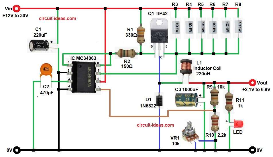
First, the circuit receives an input voltage between 12V and 30V; the MC34063 IC then starts oscillating and generates switching pulses to control the converter.
After this the pulses go to TIP42 transistor and this transistor works like current booster and because of this, high current flows in inductor L1.
Meanwhile, inductor stores energy and after that it releases energy to output side and at same time the diode D1 gives current path and this happens when transistor is OFF.
Next, capacitor C3 smooth the voltage, because of this output becomes stable DC, then feedback resistors check output voltage as IC reads this voltage and it changes duty cycle.
As a result, the circuit maintains a constant output voltage and when we adjust VR1, it changes the feedback voltage, which in turn changes the output voltage.
Formula with Calculations:
Output Voltage Formula:
Vout = 1.25 x (1 + R9 / R10 + VR1)
Values as per circuit:
- R9 is 10k
- R10 is 2.2k
- VR1 is 0 to 10k
Minimum Vout:
Vout = 1.25 x (1 + 10k / 2.2k)
Vout = 2.1V
Maximum Vout:
Vout = 1.25 x (1 + (10k + 10k) / 2.2k)
Vout = 6.9V
How to Build:
To build a 5V High Current Buck Converter Circuit using IC MC34063 follow the below connections steps:
- First, gather all the circuit parts as shown in diagram above.
- Then start with pin 1 of IC, connected to base network of TIP42 through R2.
- Next, pin 2 of IC connected to ground.
- Pin 3 of IC connected to C2 470pF to ground.
- Pin 4 of IC directly connected to system ground.
- Pin 5 of IC connected to feedback resistors R9, R10 and VR1.
- Pin 6 of IC connected to input voltage line of +12V to 30V.
- Pin 7 of IC connected to R1 to R8 resistor network one end and other end connected to +12V to 30V Vin supply.
- Pin 8 of IC connected to pin 1 of IC.
- After that, Q1 TIP42 transistors emitter pin connected to resistors network from R1 to R8, collector pin connected to inductor L1 and cathode of D1 and base pin connected to pin 1 and pin 8 of IC through resistor R2.
- No inductor L1 one end connected to to TIP42 collector and other end to output voltage.
- Also, capacitor C1 positive end connected from Vin and negative to GND and capacitor C3 positive end connected between L1 inductor and resistor R9 and negative to GND.
- At last, resistor R11 and LED, connected in series at Vout supply.
Conclusion:
Overall, this 5V High Current Buck Converter Circuit using the MC34063 IC is an excellent project for beginners because it is simple, low cost and delivers high output current.
The TIP42 transistor increases the circuits power handling capability, while the MC34063 IC provides simple and reliable control.
So this circuit is ideal for beginners and it is also, good for hobby and repair work and with with proper assembly it works reliably.

Leave a Reply