Nowadays, many electronic projects need higher voltage, however, the available supply is very low for example 3V or 3.3V batteries are common.
But many circuits need 12V so, here we have designed a 12V Boost Converter Circuit from 3.3V to 5V Supply, as this circuit increases low DC voltage to high DC voltage and therefore, it is very useful.
The circuit uses MC34063 IC which is cheap and easily available which works with low input voltage and hence, this circuit converts 3V to 12V DC easily.
Circuit Working:
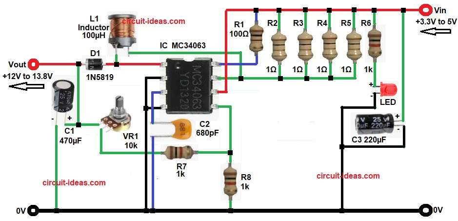
Parts List:
| Components | Values | Quantity |
|---|---|---|
| Resistors ( All resistors are 1/4 watt ) | 100Ω | 1 |
| 1Ω | 4 | |
| 1k | 3 | |
| Potentiometer 10k | 1 | |
| Capacitor | Ceramic 680pF | 1 |
| Electrolytic 470µF 25V, 220µF 25V | 1 each | |
| Semiconductors | IC MC34063 / KA34063 | 1 |
| Inductor 100µH | 1 | |
| LED any standard LED | 1 | |
| Diode 1N5819 | 1 |
The above circuit is a DC boost converter and its input voltage is from 3V to 5V DC and output voltage is adjustable up to 12V or 13.8V, also the main part of this circuit is MC34063 IC and it works as a switching regulator.
First, the circuit receives the DC input at Vin, which also powers the IC, the MC34063 IC then starts its internal oscillator and repeatedly turns its internal switching transistor ON and OFF.
When transistor is ON the current flows through inductor L1 and at this time the inductor stores energy and after that the transistor becomes OFF and now the inductor gives back stored energy.
This energy goes through diode D1 and then it charges output capacitor C1, and because of this the output voltage goes up.
Also, the feedback circuit checks output voltage, if voltage becomes high then IC reduces switching and if voltage becomes low then IC increases switching.
So, output voltage stays stable.
Formula with Calculations:
Output voltage formula:
Vout = 1.25 x (1 + VR1 / R7)
Calculation as per circuit:
where,
- R7 is 1k
- VR1 is 10k
Assume VR1 set to 8k
Vout = 1.25 x (1 + 8000 / 1000)
= 1.25 x (1 + 8)
= 1.25 x 9
Vout = 11.25V
So by adjusting VR1 output can reach 12V to 13.8V.
How to Build:
To build a 12V Boost Converter Circuit from 3.3V to 5V Supply following are the steps one needs to follow:
- Start, the circuit first by collecting all the circuit components as shown above.
- Then start with MC34063 connection pin 1 of IC connected to L1 inductor and anode of diode D1.
- Next, pin 2 and 4 of IC connected directly to ground.
- Pin 3 of IC connected to C2 capacitor and GND.
- Pin 5 of IC connected ton one end of resistor R7 and R8.
- Pin 6 of IC connected to +Vin through network of resistors from R1 to R6 and positive of capacitor C3.
- Pin 7 of IC connected to junction of R2 to R5 resistor network one end and one end of L1 inductor.
- Pin 8 of IC connected via resistor R1 to Vin.
- After that, capacitor C1 positive pin connected to the junction of one VR1 pin, cathode of D1 and Vout of 12V and negative pin of C1 goes to GND.
- Finally, LED anode connected to resistor R6 one end and cathode of LED goes to GND.
Conclusion:
To conclude, this 12V Boost Converter Circuit from 3.3V to 5V Supply is very useful project, as it is simple and reliable and also it uses minimum components.
The MC34063 IC simplifies the design, and we can adjust the output voltage with a potentiometer, as a result, this circuit suits both hobbyists and professionals and works well for low-voltage battery projects.

Leave a Reply