Many electronic projects need 12V power, but sometimes only 5V supply is available, for example from USB, logic board or microcontroller;
So, here, this Boost Converter Circuit From 5V to 12V using Transistors is useful which converts 5V DC to 12V DC.
This circuit uses simple components such as transistors and an inductor, making it low cost and easy to build; it also helps beginners learn the basics of switching circuits through hands-on practice.
Circuit Working:
Parts List:
| Components | Values | Quantity |
|---|---|---|
| Resistors (All resistors are 1/4 watt) | 3.9Ω, 470Ω, 47k | 1 each |
| 1k | 2 | |
| Capacitors | Electrolytic 10uF 25V | 2 |
| Ceramic 0.1uF | 1 | |
| Semiconductors | Transistors 2N2222, BC547, BC557 | 1 each |
| Zener Diode 12V | 1 | |
| Schottky Diode 1N5819 | 1 | |
| Inductor / Coil 330uH | 1 |
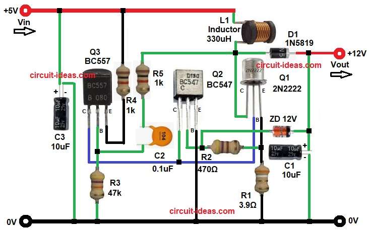
First, the circuit receives a 5V input, transistor Q3 then starts oscillating, while transistor Q2 controls and assists the switching process.
Now the signal goes to transistor Q1 and this Q1 works as main switching transistor, so Q1 turns ON and OFF very fast.
When Q1 turns ON, current flows through inductor L1, allowing it to store energy and when Q1 turns OFF, the inductor releases the stored energy, causing its voltage to increase.
Then diode D1 becomes ON, and energy moves to output capacitor C1
So output voltage goes higher and at the same time Zener diode works, it controls the output voltage and it limits voltage near 12V.
As a result, the circuit provides a stable 12V DC output.
Formula with Calculation:
Inductor current formula and calculation:
IL = Vin / L × Ton
where,
- Vin is 5V
- L is 330uH
Switching frequency estimation:
f = 1 / (Ton + Toff)
Output voltage formula for boost converter is:
Vout = Vin / (1 – D)
where D is duty cycle for 12V output:
12 = 5 / (1 – D)
1 – D = 5 / 12
D = 1 – 0.416
D = 0.584
So the duty cycle is roughly around 58 to 60 percent depending on load and component values.
How to Build:
To build a Boost Converter Circuit From 5V to 12V using Transistors we need to follow the below connections steps:
- Start, the circuit by gathering all the components as shown in circuit diagram above.
- Next, transistor Q1 2N2222 emitter pin connects to resistor R1 and ground, base pin connects to collector of transistor Q3 and collector pin connects to junction of inductor L1, diode D1 and resistor R5.
- Then transistor Q2 BC547 emitter pin connects to ground, base pin connects to anode of Zener diode and collector pin connects between base of Q1 and collector of Q3..
- After that, transistor Q3 BC557 emitter pin connects to Vin 5V supply through resistor R4, base pin connects to the junction of one end of resistor R3 and capacitor C2 and resistor R5 and collector connects to C2 and R5 network.
- Now inductor L1 one end connects to Vin 5V and other end connects to the junction of collector of Q1, inductor L1, diode D1 and resistor R5.
- Also, diode D1 1N5819 anode connects to inductor L1 and cathode connects to the junction of 12V output, cathode of Zener diode and positive of capacitor C1 .
- Further, Zener Diode ZD1 12V cathode connects to the junction of output 12V, D1 diode cathode and positive of capacitor C1 and anode connects between base of Q2 and resistor R2.
- Finally, capacitor C3 positive side connects to Vin 5V and negative to ground.
Conclusion:
Overall, this Boost Converter Circuit From 5V to 12V using Transistors is simple and useful project, as it uses easily available components and also it does not need any IC.
Therefore, this circuit offers a low cost solution for educational projects and it also helps beginners learn basic power supply concepts, making it an excellent circuit for practice.

Leave a Reply