Think Simple 3 Ampere Adjustable Power Supply Circuit using IC LM350 is like super cool power adapter for our electronics project.
Also, this circuit uses one chip called LM350 it is strong and give very good power, as tt can give power up to 3 amp and voltage we can change from 1.25V to 25V.
So we can use it for many things like to test circuit, power small motor and many thing, it is like all in one power tool for our project need.
Circuit Working:
Parts List:
| Components | Values | Quantity |
|---|---|---|
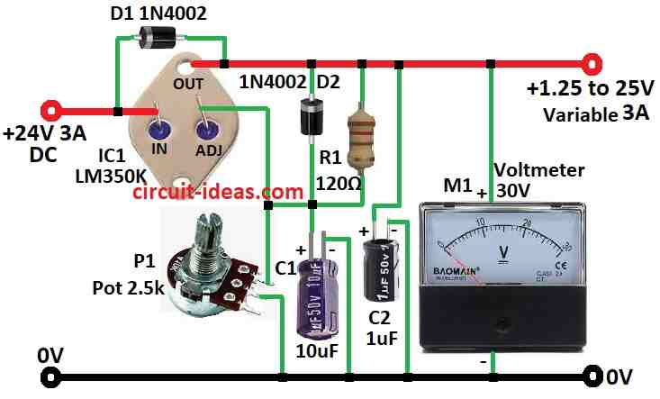
| Resistors | 120Ω 1/4 watt | 1 |
| Potentiometer 2.5k | 1 | |
| Capacitors | Electrolytic 10µF 40V | 1 |
| Electrolytic 1µF 40V | 1 | |
| Semiconductors | IC LM350K | 1 |
| Diodes 1N4002 | 2 | |
| Voltmeter 30V | 1 |
To begin with, this is small size power supply we can change voltage and it give stable power up to 3 amps, also circuit is normal type and we can adjust voltage from 1.25V to 25V.
Furthermore, main part is LM350 chip which works like power controller and strong power giver, as it also have safety inside it get too hot like 30 watts heat when it is turn OFF by itself.
To set voltage we connect “adj” pin with two resistors one fixed R1 and one adjustable P1, also there is formula to know output voltage using those resistors.
Capacitors C1 and C2 help make power more stable and diodes D1 and D2 keep chip safe when turning OFF the power.
R1 is 120 ohms and it gives small current about 3.4mA so chip works nice.
When we build this we must add big metal heatsink for LM350 it can get very hot up to 85 watts; the metal case of TO-3 type usually let heat go out at 1.5°C per watt and chip can go max to 150°C.
Hence, if we use same type of heatsink full heat resistance becomes 4°C per watt and at 30 watts heat and room temp of 25°C is inside the chip which can go up to 145°C, also at that point chip stay too hot and stop working to protect itself.
To stop chip from getting hot too fast, use smaller transformer if we only need small voltage; like if we want 9V output then do not use 25V transformer use 12V or 15V instead.
Formula:
People mostly use this formula in adjustable voltage power supplies that use the LM350 or LM317 chip and it helps them calculate the output voltage based on resistor R1 and potentiometer P1.
Formula:
Vout = 1.25V × (1 + P1 / R1)
where:
- Vout is the output voltage from regulator.
- 1.25V fixed voltage inside the chip like LM317 or LM350.
- P1 is variable resistor potentiometer which we can turn to change voltage.
- R1 normal fixed resistor.
How Formula Work:
Voltage Divider R1 and P1 make voltage divider and how much voltage go to chip depend on ratio of P1 and R1; also the place where R1 and P1 connect that voltage is 1.25V lower than output.
Adjusting Output Voltage:
When we turn P1 then voltage changes and with R1 fixed changing P1 from 0 to 2.5k ohm will change output voltage in certain range.
Important to Know:
Resistor values R1 and P1 affect how much voltage we get out.
Bigger P1 or smaller R1 = higher voltage out.
To set voltage range we choose correct values for P1 and R1 and if we want to design adjustable power supply by choosing right P1 and R1 is very important.
How to Build:
To build a Simple 3 Ampere Adjustable Power Supply Circuit using IC LM350 follow the below mentioned steps:
Making the Circuit:
- First, look at the circuit diagram to see where to put each part and then put LM350 chip on the PCB in right direction.
- Then add resistors and potentiometer R1 and P1 to make voltage control part.
- After that, place capacitors C1 and C2 and diodes D1 and D2 as shown in the diagram.
- Then check all wires and components to make sure they connect properly and remain secure.
Adding Heatsink:
- Now fix LM350 to a heatsink and use thermal paste so heat goes out better and be sure heatsink is strong and can cool chip properly.
Testing and Setting Voltage:
- Before giving power check all wiring again and there should be no mistakes or short circuits.
- After that, connect transformer to circuit for input power and slowly increase input power and watch output voltage using multimeter.
- Turn P1 potentiometer to change voltage from 1.25V to 25V.
Finishing the Building:
- After setting the right voltage fix all parts properly and cover exposed wires and add insulation and check for safety.
Using the Power Supply:
- Now the power supply is ready and we can turn P1 anytime to change the output voltage in the range.
Note:
- Always be careful with electronics and read datasheets and safety rules for each part we are going to use.
Conclusion:
To conclude, Simple 3 Ampere Adjustable Power Supply Circuit using IC LM350 is very useful and easy for hobby people and also for professionals.
Finally, it can give stable voltage from 1.25V to 25V and max 3 amps current so we can use it for many different electronic works.
Leave a Reply