Simple lead acid battery charger is very useful and it charges battery properly and make battery live longer.
These batteries are used in cars, backup power and solar storage.
This article for Lead Acid Battery Charger Circuit using IC LM350 show how charger circuit work using LM350 IC.
LM350 IC give steady and adjustable voltage and is good for charging 12V lead acid battery.
Circuit Working:
Parts List:
| Component Type | Value | Quantity |
|---|---|---|
| Resistors (All resistors are 1/4 watt unless specified) | 120Ω | 1 |
| 82Ω | 1 | |
| 10k | 1 | |
| 33k | 1 | |
| 22k | 1 | |
| Preset 2.2k | 1 | |
| Capacitors | Electrolytic 10µF 50V | 2 |
| Semiconductors | IC LM350 | 1 |
| PNP Transistor BC557 | 1 | |
| NPN Transistor BC547 | 1 | |
| LED any 5mm 20mA | 1 | |
| Diode 1N5401 | 1 |
This circuit uses LM350 and give up to 3A current.
Voltage is adjustable from 1.25V to 33V.
It give steady voltage and current to battery which help stop overcharge and make battery last long.
It works with 20V DC input.
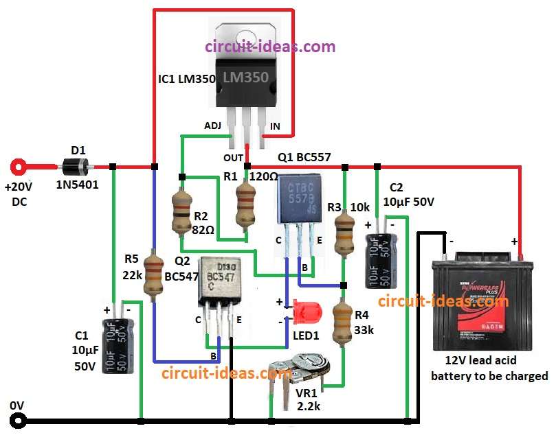
Diode D1 1N5401 used for protection if battery connect wrong way.
Main control is done by IC1 LM350 and voltage is set by resistors R1 120Ω)and R2 82Ω.
Capacitor C1 10µF keep voltage stable and remove ripple.
Transistor Q1 BC557 control charging current.
Q2 BC547 work like switch and stop charging when battery is full.
Resistors R3 10k, R4 33k, and preset R6 2.2k help with transistor work.
LED1 turns ON when charging.
When battery is full then Q2 reduces current and shows battery is charged.
This system charge battery safe and correct with controlled voltage and current.
Formulas:
Output Voltage Formula:
Vout = Vref × (1 + (R2 / R1)) + Iadj × R2
where:
- Vref is 1.25V from LM350 IC
- Iadj IS 50µA is very small which we can ignore
- R1 is 120Ω
- R2 is 82Ω
How to Build:
To build a Lead Acid Battery Charger Circuit using IC LM350 following steps need to be followed:
- Connect pin 1 ADJ of IC1 LM350 to one side of resistor R2 and other side of R2 go to emitter of Q1.
- Pin 2 OUTPUT of IC1 go to one side of R1 and other side of R1 go between ADJ pin and R2.
- Pin 3 INPUT of IC1 connect to one side of resistor R5 and other side of R5 go to base of Q2.
- Positive side of capacitor C1 go to INPUT pin of IC1 an negative side go to GND.
- Positive side of capacitor C2 go to OUTPUT pin negative side go to GND.
- Diode D1 cathode go to INPUT of IC1 and anode go to +20V DC input.
- Collector of Q1 go to positive of LED1 and negative of LED1 go to collector of Q2.
- Base of Q1 connect between resistors R3 and R4.
- One side of R3 from OUTPUT pin of IC1 other side of R3 go to base of Q1.
- R4 connect from base of Q1 to center pin of preset VR1 R6 and other pin of VR1 to GND.
- Collector of Q2 go to negative of LED1.
- Base of Q2 connect to one side of R5 and other side of R5 go to INPUT pin of IC1.
- Emitter of Q2 connect to GND.
Conclusion:
This Lead Acid Battery Charger Circuit using IC LM350 is easy and works well.
It control voltage and current keep battery safe while charging.
When battery is full circuit reduce current to stop overcharge.
With IC LM350 and transistors BC557 and BC547 it give reliable and adjustable charge.
It is good for DIY battery charger.
Leave a Reply