Think our lights are as a safety friend, this Simple Backup Light Circuit is like a good helper for our lamps, as it have two or more lights and smart system.
If one light stop working the other light turn ON by itself and there is no need to stay in dark, it is very useful in important place like hallway or in safety light.
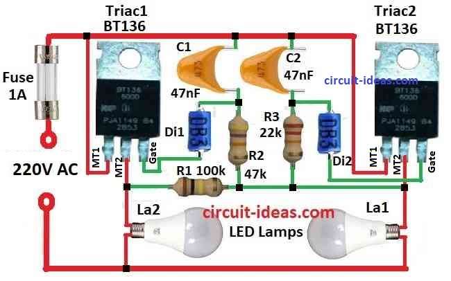
Circuit Working:
Parts List:
| Components | Values | Quantity |
|---|---|---|
| Resistors | 100k 1W | 1 |
| 47k 1/4 watt | 1 | |
| 22k 1/4 watt | 1 | |
| Capacitors | Ceramic 47nF 50V | 2 |
| Semiconductors | Triac BT136 | 2 |
| Diac | 2 | |
| LED Lamps | 2 | |
| Fuse 1A | 1 |
To begin with, this backup light circuit checks if Lamp1 stop working and Lamp2 turn ON.
But it is very important we must change Lamp1 soon if not then Lamp2 also will stop and whole circuit will not work.
Triac Tri2 connects in series with Lamp1 and R3 and C2 create the delay system.
When voltage is ON, C2 go more than 30V and Diac D2 start working and turn ON Tri2 so Lamp1 get light and Lamp2 controls part is like Lamp1 but it goes in parallel.
R2 and C1 give more delay than R3 and C2 and so Tri1 does not turn ON when Tri2 is already ON.
If Lamp1 burn out voltage goes through both delay parts using Lamp2 and R1 and Tri2 try to turn ON first, but if the current is too low so Tri2 stop working fast.
Then C1 keep charging and later Tri1 turn ON and so Lamp2 light up, because Lamp2 delay is little more it light a bit less than Lamp1.
If we want both lamps same brightness then use stronger lamp for Lamp1 higher power
Triacs can work up to 100W without heatsink and up to 1000W with heatsink and do not use bulbs less than 25W, they can be flicker.
How to Build:
To build a Simple Backup Light Circuit mentioned below are the connections steps:
Connect Lamp1 and Tri2 in series:
- First, take one wire from Lamp1 and connect to one wire of Triac Tri2 and other wire from Lamp1 connects to power source.
- Also, other wire from Tri2 also connects to other side of power source.
Add resistors and capacitors:
- Next, put resistor R1 in series with Lamp1 and Tri2.
- Connect capacitor C2 in parallel with resistor R3 and connect capacitor C1 in parallel with resistor R2.
Connect Diac to Tri2:
- One side of Diac D2 connect to where R3 and C2 join together and other side of Diac D2 connect to gate of Triac Tri2.
Note:
- This circuit give backup light and if one lamp stops other lamp turn ON so there is always light.
Conclusion:
This Simple Backup Light Circuit always keep light ON even if main lamp stop working, it switches to backup lamp by itself.
Furthermore, it uses parts like triac, diac, resistor and capacitor to check if lamp fail and when this happen it turn ON the other lamp.
Also, this circuit is very good for safe and steady light.
Leave a Reply