This Simple High Current Battery Charger Circuit is simple but works good, as it stops charging by itself when battery reaches a set voltage.
Here, the TIP35 transistor follow voltage and keeps charging voltage same and steady and this circuit is good to charge big lead acid battery.
What is a High Current Battery Charger Circuit:
This high current battery charger circuit gives enough current to charge battery fast.
However, the kind of battery like lead acid or lithium-ion and how we want to charge, it will decide how the circuit is made.
Circuit Functions:
Parts List:
| Components | Values | Quantity |
|---|---|---|
| Resistor | 50Ω 2W Resistor | 1 |
| Semiconductors | IC 7815 Voltage Regulator | 1 |
| TIP35 Transistor | 1 | |
| 12V Lead Acid Battery | 1 |
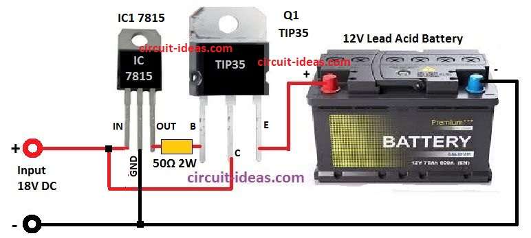
IC 7815 Voltage Regulator Functions:
- IC 7815 is voltage regulator which gives steady +15V DC.
- IC have 3 pins Vin (input), GND (ground) and Vout (output).
- Also, in this circuit 18V DC power connects to Vin pin of 7815.
TIP35 NPN Power Transistor Functions:
- TIP35 is strong NPN transistor and can handle big current up to 25A.
- It also have 3 pins Collector (C), Base (B) and Emitter (E).
- Collector connects to + side of 18V DC power and emitter connects to + terminal of big lead acid battery.
About Lead-Acid Battery:
- Big Ah lead acid battery is what we charge here, as the batteries positive terminal connects to emitter of TIP35.
Formulas:
To make high current battery charger circuit we have used some formulas:
We find charging current using battery Ah capacity and how fast maker say to charge, mostly its safe to use 0.1 times the battery Ah, example: for 100Ah battery
Charging Current (A) = 0.1 × Battery Ah
So 0.1 × 100 = 10A
Resistor for Current Limit:
In simple charger with LM317 IC we can use one resistor to control charging current.
Resistor in ohm = 1.25 ÷ Charging Current (A)
Charging Time:
This tells how long battery takes to charge, but it is only a guess not 100% exact.
Charging Time (hours) = Battery Ah ÷ Charging Current (A)
This simple formulas but help lot to design a charger.
Circuit Working:
18V DC power connects to Vin pin of IC 7815 voltage regulator and this IC 7815 changes this to steady +15V DC.
Also, this +15V from IC 7815 connects to base B of TIP35 transistor and this IC 7815 give stable voltage so TIP35 can work good and also TIP35 work like voltage follower.
Further, collector C of TIP35 connects to + side of 18V power and emitter E connect to positive terminal of lead acid battery.
When IC 7815 give +15V output it turn ON TIP35 and voltage at emitter follow base which is also around to 15V, but TIP35 drop little voltage around 0.7V so emitter gives about 14.3V.
And this 14.3V connects to the battery for charging, so the voltage stays fixed and the charging current stays the same.
Also, when battery reaches 14.3V, current stop by itself because TIP35 cannot push more voltage to battery.
How to Build:
Below are the steps to build a Simple High Current Battery Charger Circuit which are as follows.
- First, connect Vin pin of IC 7815 to + side of 18V DC power.
- Next, connect GND pin of IC 7815 to – side (ground) of power supply.
- Then, connect Vout pin of IC 7815 to base pin of TIP35 transistor.
- After that, connect collector pin of TIP35 to + side of 18V DC power.
- Also, connect emitter pin of TIP35 to + terminal of lead acid battery.
- Then put TIP35 on heat sink to stop heating problem.
- After that, connect negative terminal of battery to ground of power supply.
- Also, if needed add resistors for bias and capacitors for filter to make circuit more stable.
- See IC 7815 and TIP35 datasheets for right values and design.
Testing the Circuit:
- Turn ON the 18V DC power and use multimeter to check emitter voltage of TIP35 which should be around 14.3V.
- Then check battery voltage which should go up slowly while charging.
- And be sure charging current is safe for the battery and should not be too high.
Notes:
First, check TIP35 transistor have good heat sink to remove heat especially when charging big Ah battery.
Also, based on what is our need we must add current limiter or use power supply with current control to save battery and circuit.
Safety Precautions:
When working with high current, be careful and make sure all wires are tight and safe and keep checking the TIP35 temperature so it does not get too hot.
Conclusion:
For Simple High Current Battery Charger Circuit always read datasheet of TIP35 transistor and IC 7815 for full information and how to use properly.
We may need to change circuit a bit, based on what parts we will use and if not sure or have doubt better to ask expert or leave comment below.
Leave a Reply