Transistor 2N3055 Circuit with 1.5 Million High Gain is like normal volume knob it can make sound more but not too much and if we want very loud like 1.5 million we need to trick it little bit.
One way uses two transistors together like a double volume knob.
People also call this arrangement a Darlington pair and we can connect more of these transistor pairs together, and then the sound becomes even louder.
But making it that loud is very hard, so we need a special parts and plan it very carefully like making big concert speaker system.
Also we need to think about other things like how big sound range is and if system stays stable or not.
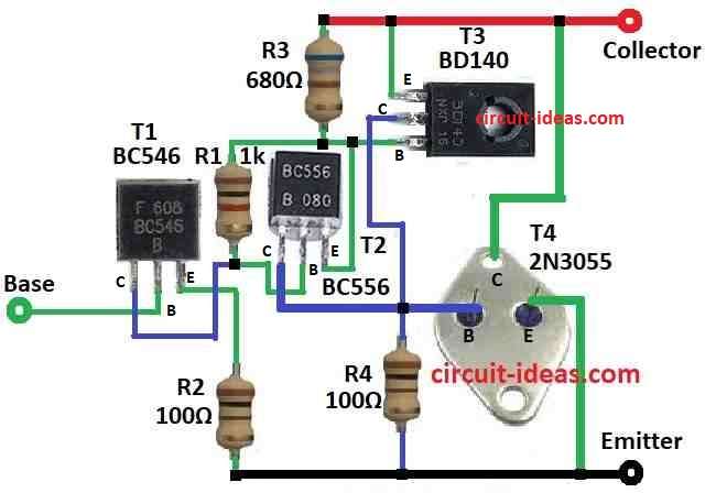
Circuit Working:
Parts List:
| Components | Values | Quantity |
|---|---|---|
| Resistors | 1k 1/4 watt | 1 |
| 680Ω 1/4 watt | 1 | |
| 100Ω 1/4 watt | 2 | |
| Semiconductors | Transistors BC546, BC556, BD140, 2N3055 | 1 each |
Sometimes we need transistor that work different than normal ones like we need more voltage, more current, more power or more gain.
Also, this we can do by using special combo of transistors and they work together like one NPN transistor.
In these circuits we have used four transistors to make one high gain NPN transistor
If we choose R1, R3 and R4 values carefully then gain can go very big which is around 1.5 million.
Furthermore, this circuit works a kind of same like 2N3055 transistor.
When temperature is 25°C it can handle power up to 115 watts.
Also, max voltage for collector is 60V and max current is 15A.
Formulas:
From diagram above we try to find voltage gain for cascade emitter followers:
When we connect 3 or more emitter follower BJTs common collector one after other, total voltage gain depends on input and output resistance.
Also each stage gain: Av1, Av2, Av3…
Voltage Gain Av:
In perfect condition each emitter follower stage gives voltage gain close to 1 the unity.
So we can say simply:
Av = 1
Input Resistance Rin:
In ideal case input resistance of one emitter follower is about same as its emitter resistor RE.
So for first stage input resistance:
Rin = RE1
where,
- RE1 is emitter resistor of first stage
Total Voltage Gain Atotal:
When we connect many emitter follower BJTs total gain usually become little less than 1 because of small losses like defects, loading.
But in ideal case if loading is very small and every stage has gain 1 then:
Atotal = Av1 × Av2 × Av3 × …
If Av = 1 for all:
Atotal = 1
Remember:
If we want exact value for voltage gain with many stages then we need to look at all things like loading, impedance etc which can be little hard.
But for most normal use we can guess voltage gain is near 1 for each stage and that is good enough.
How to Build:
To build a Transistor 2N3055 Circuit with 1.5 Million High Gain we need to follow the following steps:
NPN Version:
- Connect emitter of transistor T1 to ground using resistor R2, connect collector of T1 to base of T2 using resistor R1 and leave base of T1 open this is where input signal will go.
- Connect emitter of transistor T4 to ground and connect collector of T4 to main power supply and also base of T4 will connect to ground through resistor R4 and also connect to collector of T3.
- Connect emitter of T2 to power supply through resistor R3, connect collector of T2 to base of T4 and base of T2 connect to collector of T1.
- Connect emitter of T3 to power supply, connect collector of T3 to ground through resistor R4 and base of T3 connects to emitter of T2.
Output Connection:
- Take common point of load resistors R3 side as this go to load and other side of load connect to positive power supply.
Adjustment:
- Change values of R1, R3 and R4 to get the current gain and performance we want.
- Give signal to input then watch output, but be sure transistors do not go over their voltage, current or power limit.
Important Notes:
- Use heat sinks for transistors if working with high power and do not give big signal at input it can break the transistors.
- First, test with low voltage and current and be safe when working with electricity.
Conclusion:
To conclude, by getting very high gain like 1.5 million using normal transistors like 2N3055 is not easy, for that we need complex circuit maybe use Darlington pair or similar setup.
Also, need to design it very carefully and choose parts that match good so circuit works well and stays stable.
Leave a Reply