Car LED Voltmeter Circuit using IC LM324 is useful project to check car battery voltage, here, LEDs show different voltage which is easy to see battery condition.
Main part are LM324 op-amp which act like voltage checker and voltmeter measures voltage between two points.
Hence, this circuit is an LED voltmeter using the IC LM324 and the simple way is that LEDs show battery health fast.
Circuit Working:
Parts List:
| Components | Values | Quantity |
|---|---|---|
| Resistors (All resistors are 1/4 watt unless specified) | 15k | 1 |
| 1.2k | 1 | |
| 10k | 1 | |
| 680Ω | 3 | |
| 1k | 4 | |
| Preset 10k | 1 | |
| Semiconductors | LM324 | 1 |
| Zener Diode 5.6V | 1 | |
| LED any 5mm 20mA | 4 |
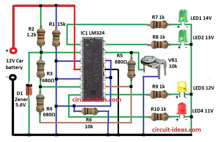
Circuit get power from car battery and it uses IC LM324 (4 op-amps) as comparators.
Then 5.6V Zener and resistor divider set reference voltage.
After that, preset VR1 adjust reference voltage and R2 to R5 set compare voltages.
Now LED1 to LED4 show battery level and each through 1k resistor R7 to R10, then comparator check battery with LED is ON if above level and OFF if below.
Further, LEDs show 14V, 13V, 12V and 11V, which means 12V or more then battery is good and 12 to 11.6V then battery is losing charge.
Finally, below 11V then battery is bad or water is low.
Formulas with Calculations:
Formulas and Calculations for Car LED Voltmeter using LM324
Voltage Divider Formula:
Used to set reference voltage.
Formula:
Vref = Vz × Rx / Rtotal
where,
- Vz is 5.6V Zener diode
Comparator Work:
Each op-amp compare battery voltage to Vref:
If Vbattery > Vref then output is HIGH and LED is ON
If Vbattery < Vref then output is LOW and LED is OFF
LED Resistor Calculation:
Use ohms law:
R = (V − Vf) / I
where:
- V is the comparator output
- Vf is the LED voltage for 2V
- I is the LED current for 10mA
How to Build:
To build a Car LED Voltmeter Circuit using IC LM324 follow below steps for connection:
- First, take all parts as in circuit diagram.
- Next, connect pin 1 of IC1 LM324 to one end of R7 and other end of R7 to LED1 anode and LED1 cathode to GND.
- Now R2 one end goes to positive supply and other end to pin 2 of IC1 and also R1 one end go to positive supply and other end to pin 3 of IC1.
- Then connect R3 between pin 2 and pin 6 of IC1.
- After that, connect pin 3, 5, 10, 12 to Non-Inverting Inputs of IC1.
- Also, connect R4 between pin 6 and pin 9 and then connect R5 between pin 9 and pin 13.
- Further, VR1 center leg goes to pin 13 and one side leg to GND.
- Connect R6 from pin 12 to GND.
- Now connect R7, R8, R9, R10 with LED1 (14V), LED2 (13V), LED3 (12V), LED4 (11V) from pin 1, 7, 8, 14 of IC1 to GND.
- Next, D1 cathode connects to pin 2 and anode to GND.
- Finally, pin 4 of IC1 goes to positive of car battery and pin 11 of IC1 go to negative of car battery.
Conclusion:
Overall, this Car LED Voltmeter Circuit using IC LM324 is simple and low cost and it uses the LM324 as four comparators.
Also, LEDs show battery voltage levels, which is the easy way to check battery health and to take care.
Leave a Reply