In this article for Multi-Tone Electronic Siren Circuit make it more fun with one siren circuit that makes many sounds.
Also, this small thing work like alarm sound toy which is good as warning.
But not just one boring sound it makes many loud noise one after one or same time!; and it works well to get people to look and listen quickly.
No more “beep beep” only now one can get big noisy siren for real attention!
Circuit Working:
Parts List:
| Components | Values | Quantity |
|---|---|---|
| Resistors | 10k 1/4 watt | 6 |
| 10Ω 1/4 watt | 1 | |
| Capacitors | Ceramic 0.22μF | 5 |
| Ceramic 0.1μF | 2 | |
| Ceramic 0.04μF | 1 | |
| Electrolytic 10μF 25V | 1 | |
| Electrolytic 220μF 25V | 2 | |
| Semiconductors | IC 4060 | 1 |
| IC 386 | 1 | |
| Coil 100μH | 1 | |
| Speaker 8Ω 1W | 1 | |
| ON/OFF Switch | 1 |
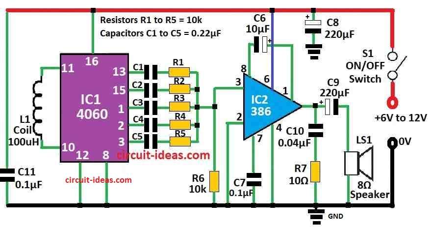
This circuit features a smart siren that we can use in many applications, such as a theft alarm or a vehicle reverse horn and it also produces five different sounds instead of just one, making the alert more noticeable and easier to hear.
Main parts are IC 4060 which makes sound and LM386 which make sound louder and together they work like magic sound maker.
Here, we have put 100μH coil before IC 4060 which helps make fast wave around 5MHz, that is radio wave speed and this IC 4060 break this wave into slower sound from which some one can hear and some too high for ones ear.
Sounds come out from pin 1, 2, 3, 13 and 15 and all those sound signals go inside LM386 chip which make them loud.
Furthermore, then this loud sound go to speaker through one part called C9 capacitor and if anyone wants more loud sound ? You can use big power amp like TBA810 or TDA1010 which will make it shout!
Also, only five outputs of IC 4060 used here and others like pin 4 to 7 and 14 make sound too high which human wont be able to hear.
Therefore, build it on small PCB board by putting it in strong box and one should give it power from battery or from 6V to 12V adaptor but clean power is always the best.
Formulas:
We can make Multi-Tone Siren using parts from the circuit diagram shown above; also its main job done is by oscillator , as it makes many sound frequencies and after that it makes sound louder and send to speaker.
How to Find Frequency:
CD 4060 chip makes sound at frequency f:
f = 1 / 2.3 × R × C
where:
- R means resistance
- C means capacitor
We can change R or C to get different sound; bigger or smaller values make low or high sound, also try different R and C and then one can get siren effect with many tones changing one by one.
Just by using different resistors and capacitors this circuit can make fun siren with many sound styles.
How to Build:
To build a Multi-Tone Electronic Siren Circuit follow these easy steps for connections:
Gather All Parts:
- First, collect all parts as shown in the diagram.
Ready the PCB:
- Next, use general purpose PCB and put all parts on it same as shown in circuit diagram.
Add IC 4060 and LM386:
- Now fix IC 4060 sound maker and LM386 sound booster on PCB and be sure one follow the pin numbers from their datasheets.
Connect Coil and C9:
- After that, solder 100μH coil at input side of IC 4060 and also connect capacitor C9 at output of IC2 LM386 which connects to the speaker.
Optional Add Power Amp:
- If anyone wants more loud sound add power amplifier like TBA810 or TDA1010 and connect it to output of LM386 but use datasheet to do this right.
Connect Speaker:
- Now wire speaker to output direct or through power amp and any one is using it.
Put in Box:
- Also, place full circuit in strong case because it keeps everything safe and looks neat too.
Give Power:
- Connect battery or power supply 6V to 12V and be sure plus and minus wires are correct if connected wrong way can break the components
Test the Siren:
- Hence, before closing the box, switch it ON and check if siren sound is working and tones are changing.
Finish Up:
- If everything good close the box tight and double check all wires are safe and nothing is loose.
Note:
- These steps help anyone build the siren easily and if we get stuck, check the component datasheets or ask an electronics expert for help.
Conclusion:
To conclude, this Multi-Tone Electronic Siren is useful little circuit; as it can make many types of sound which are good for different jobs.
Moreover, it uses parts like oscillator, divider, amplifier and speaker driver to make loud and clear tones; because it can change sound it is great for alarm alert, signal or even fun sound setups.
Finally, this small circuit can do big job and grab attention fast and send strong warning when needed.
Leave a Reply