Now one can control its own drill; in this article for AC Drill Speed Controller Circuit is like cruise control but for drill.
Furthermore, it helps one to change motor speed, so one can work better for any job, also very good when one is doing soft work like wood or metal but need careful hand.
Hence, there is no need for full speed all the time but one can slow down for better cut, no break and no mess.
Circuit Working:
Parts List:
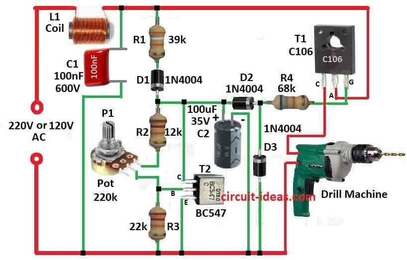
| Components | Values | Quantity |
|---|---|---|
| Resistors (All resistors are 1/4 watt unless specified) | 39k | 1 |
| 12k | 1 | |
| 22k | 1 | |
| 68k | 1 | |
| Potentiometer 220k | 1 | |
| Capacitors | PPC 100nF 600V | 1 |
| Electrolytic 100µF 35V | 1 | |
| Semiconductors | SCR C106 | 1 |
| Transistor BC547 | 1 | |
| Diodes 1N4004 | 3 | |
| Inductor Coil 40µH 5 Amp | 1 | |
| Drill Machine (220V) | 1 |
To begin with, this circuit is good for controlling the drill speed even if the drill works hard or light; it work because when drill get more load the back EMF go down and then current go up.
If look at the circuit diagram, one can see it not very hard but easy to understand and build.
When mains voltage go positive capacitor C2 charge through R1 and D1 it stop charging when voltage same as Zener voltage set by T1; also, T1 use Zener idea and voltage depends on how one sets P1.
Voltage between collector and emitter come from ratio of R3 and (R2 + P1), because drop on R3 always 0.6V (base emitter voltage of T1) then Zener voltage is 0.6V times (P1 + R2 + R3).
Moreover, motor shown as R3 in diagram not in front but come after C106 and T1, also C106 fire time depend on difference between zener voltage and motors back EMF.
Therefore, if motor get more load SCR fire early; but SCR only control 180 degree of power cycle so one cannot get speed from 0 to full 100% but only partial control.
The circuit still works well for low-speed operation; however, it drives the motor with a slight jerk at no load and runs more smoothly under load.
L1 and C1 used to clean up noise from chopping the phase; as SCR heats up it requires heat sink for cooling.
Formula:
For making simple adjustable zener circuit using transistor and resistors follow the below formulas:
Basic Idea:
We use transistor (like emitter follower) one resistor in series and one for zener diode.
Make it Adjustable:
We can change zener diode or resistor R1 to get different output voltage (Vout).
How to Know Output Voltage:
If the transistor operates normally and the circuit remains stable, we can expect the output voltage to behave like this:
Vout = VZD − VBE
where,
- VZD voltage of zener diode (fixed),
- VBE is base emitter drop of transistor which is around 0.6V for silicon like BC547.
So by changing R1 or using other zener diode with different voltage we can change Vout.
What to Think When Building:
Choose good transistor for the voltage and current and pick resistor values carefully so that circuit is not unstable or too hot.
Also, if circuit uses more power think about heat sink to cool down transistor.
Last Note:
We can easily build this simple circuit with readily available parts and we can change the resistor or Zener diode to obtain the desired voltage for different applications.
How to Build:
To build a AC Drill Speed Controller Circuit follow the below steps:
Get Components:
- First, collect all parts one needs as per the listed components in the circuit diagram above
Place on Board:
- Next, put parts on circuit board same like in diagram.
Connect Power:
- Then join power to circuit and check the wires go right way
Add Capacitors and Resistors:
- After that, put capacitor C2 in parallel with power supply and then connect resistor R1 and diode D1 in series and put across C2.
Add Zener Diode T1:
- Also, connect Zener diode T1 to circuit and be sure it face correct way like in diagram.
Set Adjustable Zener:
- Now connect potentiometer P1 as it controls the Zener voltage and wire it so it changes voltage on zener.
Connect SCR C106:
- Add SCR C106 in right place and connect gate pin of SCR as shown in diagram.
Add Motor:
- Motor shown as R3 connect after SCR C106 and check wiring is correct.
Add Filter Parts:
- Put inductor L1 and capacitor C1 in circuit and they clean high frequency noise and connect them as in diagram.
Cool Down:
- Put SCR C106 on heat sink and get hot when working.
Test Circuit:
- Check all wires again, power on the circuit and verify that we can change the drill speed; also ensure the drill maintains the same operation even under increased load.
Fine Tune:
- Turn potentiometer P1 to get Zener voltage one needs and adjust for best performance.
Note:
- Finally, be safe when working with electricity and if one is unfamiliar with electronics ask expert or someone who knows.
Conclusion:
To conclude, AC Drill Speed Controller Circuit gives more control to user who can change drill speed easily so one can work better and faster in many jobs.
Leave a Reply