Car Antenna Amplifier Circuit is a small box that helps the car radio catch signals better; also, radio signals are sometimes very weak like a soft whisper, so the radio does not hear them clearly.
Amplifier make whisper loud so radio can hear clear, it is good for places where radio station is far or music have noise or crack sound.
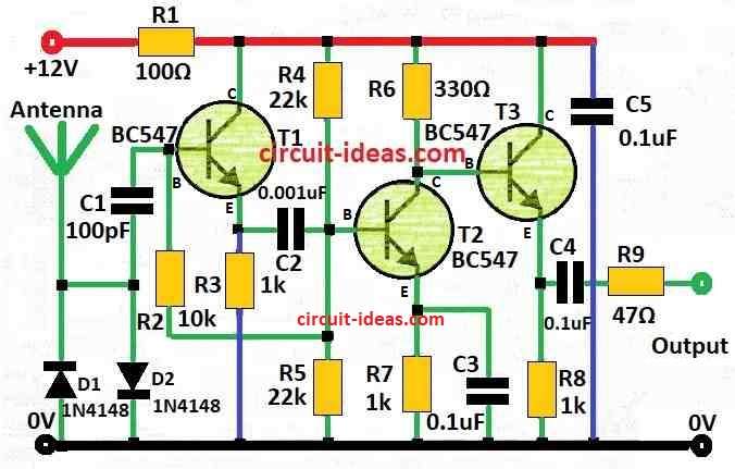
Circuit Working:
Parts List:
| Components | Quantity |
|---|---|
| Resistors ( All resistors are 1/4 watt unless specified) | |
| 100Ω | 1 |
| 10k | 1 |
| 330Ω | 1 |
| 47Ω | 1 |
| 1kΩ | 3 |
| 22k | 2 |
| Capacitors | |
| Ceramic 100pF | 1 |
| Ceramic 0.001µF (1nF) | 1 |
| Ceramic 0.1μF | 3 |
| Semiconductors | |
| Transistors BC547 | 3 |
| Diodes 1N4148 | 2 |
| Antenna | 1 |
This amplifier for car antenna can work up to 70 MH which helps make weak signal more strong from the antenna; also it have high input impedance and make little noise.
Here, gain is around 30 dB which is at 30 MHz and input impedance is about 10 kilo ohm and to stop signal loss from coax cable better to put amplifier right at bottom of antenna.
Also, this amplifier works only for fixed receivers and is not good for moving or driving use.
Since, if one puts it outside on antenna please cover with waterproof box or rain can break it.
Important: This amplifier is only for receiving signal is anyone trys to send signal through it the parts can break.
Formula:
Making a circuit to boost weak RF signal from antenna is the job of building amplifier using BC547 transistors for car antenna.
Gain of Amplifier (Common Emitter type):
To guess voltage gain (Vg) we can use this:
Av = −RC / re
where:
- RC is resistor on collector side
- re is small resistance from emitter and we get it from: re = VT / IC
- VT is about 26mV at normal temperature
- IC is current going in collector
How we connect the transistors and apply the bias decides the actual gain.
Note:
With BC547 transistor this circuit gives simple base for making amplifier for car antenna; but for better working in actual car radio or similar use one needs to test more and maybe change some parts.
How to Build:
To build a Car Antenna Amplifier Circuit follow the below steps for connections and safety:
- First, select the right parts based with the elements listed in the description and the frequency range one wants to use.
- Be sure design is okay for frequency and impedance.
- Next, put parts on board same like in circuit diagram and be careful with ground and RF wire to stop signal problem.
- After that, solder all the parts on PCB one by one, then take care with small parts like transistor and capacitor whether they break easy.
- Now put the amplifier close to car antenna base and then fix it well so it does not move or come loose.
Testing the circuit:
- Connect power and test with car antenna and also use RF tools like signal generator or spectrum analyzer to check the gain and frequency.
Final Check:
- After building and mounting the circuit, test the full circuit and check if it works properly and matches the required performance.
Note:
- Be safe while soldering and testing as RF circuits can be sensitive.
- Also, check with all wire and parts again because small mistake can make amplifier not work good, so to avoid any errors that could affect the performance of the amplifier.
Conclusion:
Overall, people mostly place the Car Antenna Amplifier Circuit near the antenna and very close to the antenna base, also, this helps stop signal loss in the coax cable connected to the car radio.
Moreover, designers make some amplifier circuits specially for certain antenna types or specific frequencies based on how users want to use them.
In general car antenna amplifier can make car radio work much better, as it help catch more stations and give more clear sound while driving.
Leave a Reply