In this article, resistors can provide basic speed control, but they cannot adjust motor speed efficiently or smoothly.
Therefore, this smart PWM Motor Speed Control Circuit using Two Transistors offers a more effective solution.
It works like a dimmer switch for the motor and we can turn a knob like a potentiometer to change how much power the transistors get; also this controls the motor speed.
Circuit Working:
Parts List:
| Components | Values | Quantity |
|---|---|---|
| Resistors (All resistors are 1/4 watt unless specified) | 22k | 1 |
| 220Ω | 1 | |
| 47Ω | 1 | |
| Potentiometer 10k | 1 | |
| Capacitors | Electrolytic 100µF 25V | 1 |
| Semiconductors | Transistor BC557 | 1 |
| Transistor BC338 | 1 | |
| DC Motor | 1 |
This is a simple motor speed controller using two transistors and it is better than using a resistor for two main reasons:
Resistors waste energy as heat but this circuit sends most of the power directly to the motor and resistors can make the motor start roughly while this circuit runs it smoothly.
Also, the circuit uses PWM (Pulse Width Modulation) to control speed, as it turns the motor ON and OFF very quickly.
The longer it is ON higher duty cycle and the faster the motor runs and shorter it is ON lower the duty cycle and slower it goes.
Hence, this fast switching makes the motor run smoothly.
How the circuit works:
The circuit uses two transistors, a PNP BC557 and an NPN BC338, arranged as a Darlington pair to increase current gain and enable the circuit to drive larger motors.
Furthermore, a potentiometer controls the motor speed and by turning the knob changes the voltage at the NPN transistors base.
As a result, this controls how much current flows through the motor and by adjusting its speed.
Formulas:
This circuit controls the DC motor speed using PWM (Pulse Width Modulation).
Duty Cycle Formula:
We can calculate the duty cycle (D), which shows how long the signal remains ON, using the following formula:
D = (Rpot / (Rpot + Rfixed)) × 100%
- Rpot is the variable resistance from the potentiometer from 0 to 10kΩ.
- Rfixed is the value of the fixed resistor in the circuit.
Motor Speed Control:
The motor speed depends on the average voltage from the PWM signal.
A higher duty cycle means more voltage and faster speed and a lower duty cycle means less voltage and slower speed.
Important Notes:
Use the correct transistors like BC338 to control motor current and BC557 to generate the PWM signal, also we can add a capacitor to smooth out the PWM signal.
Choose resistor values that match the transistors current gain β so they get enough base current, hence this circuit works using just transistors and a few basic parts.
How to Build:
To build a PWM Motor Speed Control Circuit follow the below mentioned steps for assembling:
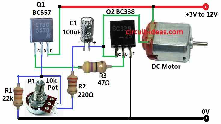
- First, join Q1s collector to Q2s base using resistor R3, then connect Q1s base between resistor R1 and P1 potentiometer and then link Q1s emitter to the positive (+) power supply.
- Next, connect Q2s collector to one wire of the DC motor, then join Q2s base to Q1s collector and connect Q2s emitter to ground (-).
- Now connect one side of capacitor C1 to Q2s collector and the other side to the potentiometer through resistor R2.
- Also, connect other wire of the DC motor to the positive (+) power supply.
Note:
- Want more features? like reverse motor or protect from overload then use motor driver ICs, but be careful and handle electrical parts safely.
Conclusion:
Overall, using resistors to slow down motor is easy but it wastes power and makes motor run rough, but using two transistors is better and it saves power.
Also, with potentiometer we can change motor speed slowly and smoothly; hence, this PWM Motor Speed Control Circuit using Two Transistors is a good and easy choice for simple motor speed control.
Leave a Reply