Simple TDA7274 Based Low Voltage Motor Speed Controller Circuit is useful and easy to make, as the circuit is efficient and precise with speed adjust.
Also, TDA7274 IC is motor driver for low voltage and for low power DC motors and it works from 1.8V to 6V and has built-in voltage reference.
Furthermore, output is up to 700mA and is stable with temperature change, Vs supply choose as per motor need from 1.8V to 6V and finally, max output current is about 700mA.
Circuit Working:
Parts List:
| Components | Values | Quantity |
|---|---|---|
| Resistors | 220Ω, 2k 1/4 watt | 1 each |
| Potentiometer 10k | 1 | |
| Capacitors | Electrolytic 4.7µF 25V | 1 |
| Electrolytic 1µF 25V | 1 | |
| Semiconductors | IC TDA7274 | 1 |
| DC Motor | 1 |
To begin with, circuit uses TDA7274 to control motor speed by input voltage.
R1, R2 and VR1 adjust control voltage for accurate speed and TDA7274 IC1 manage power to motor and then R1, R2 and VR1 make voltage divider to change control signal.
Also, C1 and C2 cut noise and keep circuit smooth and then motor get correct voltage for different speeds.
Formula:
Below are the formulas with calculations for Simple TDA7274 Based Low Voltage Motor Speed Controller Circuit:
Voltage divider formula:
Vcontrol = Vs × (VR1 / (R2 + VR1))
where:
- Vcontrol is voltage to control pin
- Vs is the supply voltage
- R2, VR1 are the voltage divider parts.
How to Build:
Below are the steps for to build a Simple TDA7274 Based Low Voltage Motor Speed Controller Circuit:
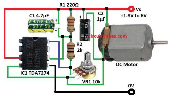
- First, gather all the parts as per the circuit diagram
- Next, connect pin 3 of IC1 to the positive supply.
- After that, connect pin 4 of IC1 to one end of VR1.
- Now connect pin 5 of IC1 to ground.
- Then connect pin 6 of IC1 between R1 and R2 and also, connect pin 8 of IC1 between R2 and VR1.
- Further, connect the positive side of capacitor C1 to the positive supply and the negative side goes to pin 6 of IC1.
- Also, connect one end of the DC motor to the positive supply and the other end goes to pin 4 of IC1.
- Finally, connect the positive side of capacitor C2 to the positive supply and the negative side go to pin 4 of IC1.
Conclusion:
Overall, Simple TDA7274 Based Low Voltage Motor Speed Controller Circuit is build easily, also the speed changes by adjusting the resistors.
In addition, the circuit is simple and requires no complex parts, also it works well for small motor projects and provides stable, adjustable speed control.
Leave a Reply