Do anyone want to play drums but do not have full drum kit? then this Electronic Drums Simulator Circuit can help as it work like small electronic drum.
Also, it uses smart parts to make drum sound like kick and snare; sound come from electronics and not from real drum.
Furthermore, it can make sound using things like relaxation oscillator like build and drop sound or twin T oscillator which is another sound maker.
Circuit Working:
Parts List:
| Components | Values | Quantity |
|---|---|---|
| Resistors (All resistors are 1/4 watt unless specified) | 100k | 2 |
| 22k | 2 | |
| 47k | 4 | |
| Potentiometer 25k | 2 | |
| Capacitors | Ceramic 10nF | 3 |
| Ceramic 4.7nF | 2 | |
| Ceramic 22nF | 1 | |
| Semiconductors | Transistor BC547 | 2 |
| Touch Pads | 4 |
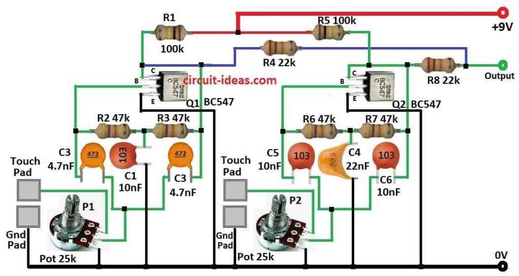
This circuit uses two twin-T oscillators, also they use transistors Q1, Q2 BC547 with some resistors and capacitors.
Twin-T is good for stable sound and in this circuit they are almost ready to start but just need small push.
When we touch the pad it connect base of transistor to ground and then transistor start working and it turns ON the oscillator.
Each oscillator make different drum sound depending on parts used and we can change pitch tone using two 25k pots like P1 and P2.
Hence, to play, just touch a pad it make that drum sound come from speaker and touch pads becomes fast one after other to make drum beats.
For drum, roll slide finger across pads quickly which will make fast drum sound.
Formulas:
This circuit use special setup of resistors, capacitors and transistors to make Twin-T oscillator, as it makes steady sound at set frequency.
Twin-T use feedback parts R1, C1, C2 to keep sound going and these parts decide the frequency, also it works using positive feedback.
Formula for frequency (f in Hz) is:
f = 1 / 2πRC
where:
- R is resistance and here in this circuit it is pot P1
- C is capacitance and in this circuit it is C1 and C2 = 4.7nF capacitors like C3
Note:
This design is good for making sound in electronic drums and we can change frequency by changing R or C to get different drum sounds.
How to Build:
To build a Electronic Drums Simulator Circuit follow the below mentioned steps:
Transistors Connections:
- First, Q1 BC547 base goes to touch pad, collector goes to point between R2 47k and C2 4.7nF and emitter goes to ground.
- Then Q2 BC547 base goes to touch pad, collector goes to point between R7 47k and C4 22nF and emitter goes to ground.
Resistors Connections:
- After that, R1 100k connects from 9V battery + to circuit, R2 47k connects between base of Q1 and C2 4.7nF, R5 22k goes to output, R7 47k connect between base of Q2 and C4 22nF and R8 47k connects from collector of Q2 to output.
Capacitors Connections:
- Now C1 10nF connect from R2 47k to ground, C2 4.7nF connect between Q1 collector and R2 and C4 22nF connect between base of Q2 and R7.
Note:
- Always check wiring before turning power ON and use right parts for our voltage.
Conclusion:
To conclude, the Electronic Drums Simulator Circuit offers a fun and educational way to learn electronics.
Although it does not produce highly realistic drum sounds, but it helps users understand how electronic circuits generate sound.
Leave a Reply