Imagine we have normal car battery and we want to use it for fluorescent light, but the battery voltage is too low and it does not work like this.
So we use special and Simple 20 Watt Fluorescent Inverter Circuit like a magic box and this box has transformer, transistor and other parts which change low voltage to high voltage.
High voltage zap makes fluorescent light turn ON and this zap is a AC which goes both ways but a not a DC which is one way like battery.
Circuit Working:
Parts List:
| Components | Values | Quantity |
|---|---|---|
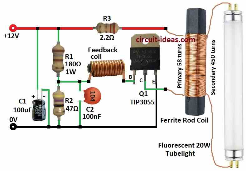
| Resistors (All resistors are 1/4 watt unless specified) | 180Ω 1W | 1 |
| 47Ω | 1 | |
| 2.2Ω | 1 | |
| Capacitors | Ceramic 100nF | 1 |
| Electrolytic 100µF 25V | 1 | |
| Semiconductors | Transistor TIP3055 | 1 |
| Inductors/Coils Feedback Coil | 1 | |
| Ferrite Rod Coil (as per text) | 1 | |
| Fluorescent 20W Tubelight | 1 |
To begin with, this circuit can run a 20-watt tube light and below is how it works:
We wound the transformer on a ferrite rod measuring 10 mm in diameter and 8 cm in length.
Although the wire size is not critical, we used 0.61 mm wire for the primary winding and 0.28 mm wire for the secondary and feedback windings.
Remember, do not remove the tube while circuit is ON because high voltage spikes can break the transistor, also circuit uses around 1.5 amps at 12V which is better than using mains power.
Also, normal tube light takes 20W + 15W for ballast but this circuit saves power.
Formulas:
When making a fluorescent tube driver using one BJT and a transformer we have build a high-frequency oscillator.
Here is the main formula:
Resonance frequency (f):
f = 1 / (2π√L * C)
- L is the Inductor like coil
- C is the Capacitor
In BJT base circuit frequency depends on L and C and the BJT makes a stable AC signal at this frequency and this helps tube light to work properly.
Note:
Using one BJT and transformer is simple and works well, as it uses resonance between L and C to keep AC signal steady at right frequency.
How to Build:
To build a Simple 20 W Fluorescent Inverter Circuit follow the steps mentioned below for connections:
Transformer:
- First, primary coil goes to battery (+) through resistor R3 for safety and then secondary coil connects to transistor Q1s collector.
Transistor Q1 Connection:
- Then base gets power from resistors R1 and R2 as a voltage divider, collector connects to transformers secondary and then emitter goes to ground (–)
Capacitors Connection:
- After that, C2 connects from feedback coil to transistor base and other side goes to ground and C1 connects across battery (+) and (–) for smoothing.
Fluorescent Tube:
- The circuit connects this component to the secondary side of the transformer.
Resistors Connection:
- R1 and R2 connect between the batteries positive (+) and negative (–) terminals, while R3 acts as a safety resistor and connects to the batteries positive (+) terminal.
Important Safety Tips:
- Use parts with correct voltage/current ratings.
- Solder carefully bad joints can break the circuit and cover bare wires and avoid short circuits.
- Never run the circuit without the tube connected as it can kill the transistor and if anyone is unsure ask someone with experience.
Conclusion:
Overall, this Simple 20 Watt Fluorescent Inverter Circuit lets us run a tube light from a battery, it uses a transformer, one transistor and a few parts to change DC (battery) to high voltage AC.
Also, it is simple project but we need to be careful as high voltage is dangerous.
Leave a Reply