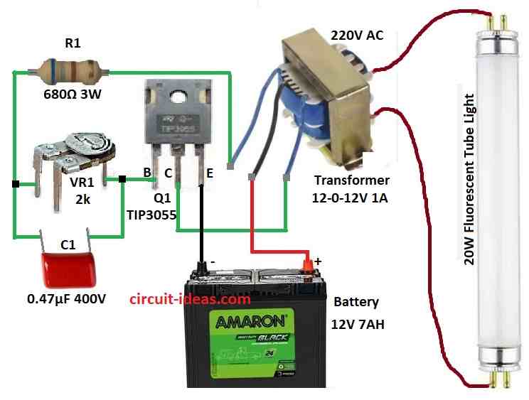
A circuit for emergency tube lights is a crucial tool that offers lighting during electricity failures.
This project aims to utilize a few components and provides an effective solution for lighting emergencies.
The main components of the circuit consist of a step-down transformer, a pulse switching circuit and a fluorescent tube lamp.
This article describes the operational principle and design of a basic emergency tube light circuit.
Circuit Working:

Parts List:
| Component | Descriptions | Quantity |
|---|---|---|
| Resistors | ||
| Resistor | 680Ω, 3W | 1 |
| Variable Resistor (Preset) | 2k | 1 |
| Capacitor | ||
| PPC Capacitor | 0.47µF, 400V | 1 |
| Semiconductors | ||
| Transistor | TIP3055 | 1 |
| Other Components | ||
| Step-Down Transformer | 12-0-12V 1AH | 1 |
| Battery | 12V, 7AH | 1 |
| Fluorescent Tube Light | 20W | 1 |
In this circuit, a 12-0-12V configured step-down transformer is employed as the transformer for driving the fluorescent light.
The terminals of the primary winding are linked to a 20-watt fluorescent lamp while the center-tapped secondary terminals are connected to the switching pulse circuit.
The functioning of the circuit is detailed as follows:
A capacitor C1 and a variable resistor preset VR1 create the switching pulse generator.
These elements influence the timing and frequency of the pulses.
The produced pulses are fed to the base of a power transistor Q1 TIP3055.
This transistor functions like a switch, continually linking and unlinking the transformers secondary winding to the battery source.
The switching process generates an electromagnetic force EMF within the transformer windings.
This EMF is increased in the primary winding generating enough voltage to power the 20 watt fluorescent light.
Formulas and Calculations:
Below are the comprehensive formulas and calculations for the emergency tube light circuit:
Oscillation Frequency Formula:
f = 1 / (2 * π * R * C)
where,
- f represents the frequency in Hz
- R represents resistance in ohms
- C represents capacitance in farads
Calculations:
R = 2k and C = 0.47µF (0.47 * 10^-6 F)
f = 1 / (2 * 3.1416 * 2000 * 0.47 * 10^-6)
f = 169.6 Hz
Power Delivered to Fluorescent Tube Formula:
P = V * I
where,
- P is power in watts
- V is voltage in volts
- I is current in amperes
Calculations:
if V = 220V and I = 1.67A
20 = 220 * I
I = 20 / 220
I = 0.09 Amp
How to Build:
To build a Practical Emergency Tube Light Circuit follow the below mentioned connections steps:
- Gather all the components as mentioned in the above circuit diagram.
- Connect base of transistor TIP3055 to one end of variable resistor VR1 and other end of VR1 is connected to one end of R1.
- Connect the other end of resistor R1 to one wire of transformer as shown in above diagram
- Connect collector of transistor TIP3055 to one wire transformer.
- Connect emitter of transistor TIP3055 to negative supply of 12V battery.
- Connect capacitor C1 is connected across the terminals of VR1.
- Connect the center wire of transformer to the positive supply of 12V battery
- Connect the 20W fluorescent tube light with the secondary 220V wire of the transformer.
Conclusion:
This functional emergency tube light circuit serves as an economical option for emergency illumination.
Using fundamental elements like a step-down transformer, a variable resistor, a capacitor, and a power transistor, the circuit effectively powers a 20-watt fluorescent light.
This design is perfect for DIY lovers and offers a dependable light source during power failures.
Leave a Reply