In this post we will see how to make Simple Contactless 220V Phase Detector Circuit using IC 4017, as this small tool help to check wire or cable if current is inside or not without touching it.
Also, this circuit is very useful for electrician to find problem in big electric system; if current is there in wire the light will glow by indicating it with an LED.
Circuit Working:
Parts List:
| Components | Values | Quantity |
|---|---|---|
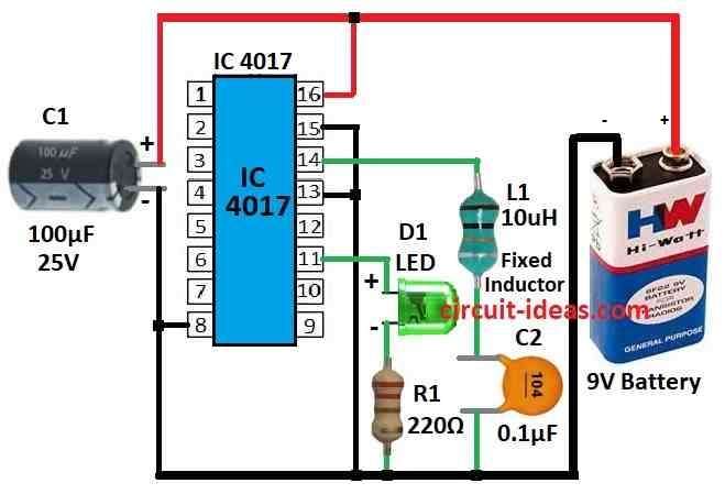
| Resistor | 220Ω 1/4 watt | 1 |
| Capacitors | Ceramic 0.1µF | 1 |
| Electrolytic 100µF 25V | 1 | |
| Semiconductors | IC 4017 | 1 |
| LED Green 5mm 20mA | 1 | |
| Fixed Inductor 10uH | 1 | |
| Battery 9V | 1 |
To begin with, this circuit can find AC power in wire from one foot away it can sense AC signal (hum) near power wire and shows it by turning ON the LED.
The circuit uses the CD4017 IC, which is a counter chip with 10 outputs.
Pin 14 of this IC is very sensitive; it receives the signal (e.m.f.) and makes the output pins go high one by one, however, the IC works only when pin 15 connects to ground.
Furthermore, in this circuit we have used only pin 11 to glow LED.
Coil L1 takes signal from power wire and sends it to IC and then IC makes LED blink fast and to use it just keep the circuit near the power wire and there is no need to change anything.
Therefore, if LED turns ON it means wire has current and if LED stays OFF then there is no current in wire.
Formulas:
This circuit counts the pulses from a voltage divider connected to 220V AC using CD 4017 chip, the voltage divider makes high AC voltage low which is safe for the IC.
Also, the CD 4017 gets pulses from both up and down swings of AC power and by counting these pulse the circuit can tell the phase of AC voltage.
Capacitor Reactance:
Capacitor C2 shapes the pulse received by the CD 4017, this phenomenon is called reactance, which we can calculate using the formula:
XC = 1 / (2 × π × f × C)
where,
- XC is reactance in ohms
- π is about 3.14
- f is frequency of AC from 50Hz or 60Hz
- C is value of capacitor in this circuit which is 0.1uF
Resonance Frequency:
To find the frequency where capacitor and inductor work together in LC circuit we can use this formula:
f = 1 / (2 × π × √(L × C))
where,
- f is frequency in hertz (Hz)
- L is inductance in henrys which is the value of L1
- C is capacitance in farads the value of C1
Note:
The L1 coil in this circuit does not need an exact value because it mainly limits large current and works as a filter.
Also, designers usually choose the value of L1 based on size, cost or current-handling capacity instead of any strict formula.
How to Build:
To build a Simple contactless 220V Phase Detector Circuit follow the below mentioned assembling steps:
- First, put IC CD 4017 on breadboard or PCB and then connect pin 16 VDD to positive of power and connect pin 8 to ground.
- After that, take LED connect long leg anode to pin 11 of IC using 220 ohm resistor and short leg cathode goes to ground.
- One side of L1 connect to power wire of device and the other side connect to pin 14 of IC.
- Also, connect pin 13 and pin 15 to ground.
- Now give power to the circuit and be sure the voltage is correct for parts one uses.
- Now bring this circuit near power wire and if all is ok then LED will turn ON when AC current is inside the wire and if LED does not glow then check all wires and parts again.
Adjustments:
- If LED does not work well we can adjust to get better result.
Note:
- Be careful! this circuit works near high voltage AC and if anyone does not know about electronics well take help from someone who does.
Conclusion:
To conclude, this Simple Contactless 220V Phase Detector Circuit using IC 4017 is simple and useful, as it can find AC voltage in wire or cable without touching it.
Also, very helpful for checking and finding live wires in home or office wiring, as it gives safe and easy way to know if AC voltage is present in them.
Leave a Reply