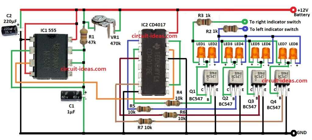
Car Turn Signal Circuit with Chasing Effect is important project for electronic, in which it shows if driver turn left or right; also this circuit make lights blink one by one like in new cars.
Moreover, it uses two main parts: 555 timer IC and CD 4017 counter IC.
First IC1 make blinking signal and then this signal goes to second IC2 to move lights in order.
Hence, this explains how the car turn signal circuit works and how we can build it using the 555 timer and CD4017 ICs.
Circuit Working:
Parts List:
| Components | Values | Quantity |
|---|---|---|
| Resistors | 47k 1/4 watt | 1 |
| 1k 1/4 watt | 2 | |
| 10k 1/4 watt | 4 | |
| Preset 470k | 1 | |
| Capacitors | Electrolytic 1μF 63V | 1 |
| Electrolytic 220μF 25V | 1 | |
| Semiconductors | 555 Timer IC | 1 |
| CD 4017 Decade Counter IC | 1 | |
| Transistors BC547 | 4 | |
| LEDs Any 5mm 20mA | 8 |
This circuit uses two main ICs like 555 timer IC1 and CD4017 counter IC2.
IC1 work in astable mode as it make square wave signal again and again and this signal control how fast LEDs blink.
Further, parts R1, R2 and C1 set the speed and then IC1 send clock pulse to pin 14 of IC2.
After that, IC2 counts the pulses and turns ON the output pins one by one.
The circuit uses only the first eight outputs (Q0 to Q7) to light LEDs LED1 to LED8, but however, IC2 cannot supply enough current to drive the LEDs directly.
So we use transistors BC547 from Q1 to Q4 to give more current and each transistor control 2 LEDs.
When IC2 change outputs the LEDs blink in chasing style like moving turn signal and hence, to choose left or right signal use cars normal turn switch.
Note: Be careful with wiring as wrong connection can damage cars electric system.
Formulas:
Formula and Calculation for Car Turn Signal with Chasing Effect:
555 Timer Frequency Formula (Astable Mode):
f = 1.44 / ((VR1 + 2R2) × C1)
where:
- VR1 is the preset for adjustable resistor
- R2 is the fixed resistor 47k
- C1 is the capacitor 1µF
How to Build:
To build a Car Turn Signal Circuit with Chasing Effect follow the below steps mentioned:
- First, gather the circuit parts as per in circuit diagram
- Next, connect pin 1 of IC1 555 to GND.
- After that, connect pins 2, 6, 7 of IC1 to one side of R1 and other side of R1 goes to middle pin of VR1 and second pin of VR1 goes to positive supply.
- Then connect positive of C1 to pins 2, 6, 7 of IC1 and negative of C1 goes to GND.
- Now pin 3 of IC1 connect to pin 14 of IC2 CD 4017.
- Also, pins 4 and 8 of IC1 go to positive supply.
- Finally, positive of C2 connect to +12V and negative of C2 to GND.
Connections with IC2 CD 4017:
- Now pin 2 of IC2 goes to base of Q2 via resistor R5.
- Then pin 3 of IC2 goes to base of Q1 via resistor R4.
- Also, pin 4 of IC2 goes to base of Q3 via resistor R6.
- Further, pin 7 of IC2 goes to base of Q4 via resistor R7.
- Next, pins 8 and 13 of IC2 connects to GND.
- Then pin 10 connect to pin 15 and finally, pin 16 connect to +12V.
Transistors and LEDs:
- Emitters of Q1 to Q4 go to GND, collectors of Q1 to Q4 connect to cathode of LEDs LED1 to LED8.
- Also, same cathodes of LEDs go to left indicator switch via R2 and positive of anodes LEDs go to right indicator switch via R3.
Conclusion:
To conclude, this Car Turn Signal Circuit with Chasing Effect use 555 timer and CD 4017, it make LEDs blink one by one; also it is easy to build, cheap and useful.
As a result, we can adjust the blink speed and we can use this circuit for car signals, decorative lights and other alert systems.
Leave a Reply