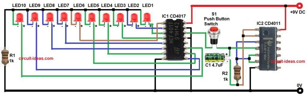
This circuit is for simple Random LED Number Generator Circuit using IC CD4017 decade counter and IC CD4011 NAND gate; also it works on 9V power supply and the LEDs in the circuit represent the numbers.
When we press the switch, one LED remains ON, because the counter runs very fast and the final LED looks random.
Therefore, this circuit works like an electronic dice which is simple to build and is useful for games, school projects and learning digital electronics.
Circuit Working:
Parts List:
| Components | Values | Quantity |
|---|---|---|
| Resistor | 1k 1/4 watt | 2 |
| Capacitor | Electrolytic 4.7uF 25V or higher | 1 |
| Semiconductors | IC CD4017 Decade Counter | 1 |
| IC CD4011 Quad NAND Gate | 1 | |
| LED 5mm any color | 10 | |
| Push Button Switch | 1 | |
| Power Supply 9V Battery or 9V DC Adapter | 1 |
To begin with, applying the 9V power supply activates the CD4011 IC.
Two NAND gates then operate as an astable multivibrator and generate continuous clock pulses and then resistor R1 and capacitor C1 show the pulse frequency.
If R1 value increases then the speed becomes slow and similarly if C1 increases then delay becomes more.
Now these clock pulses go to pin 14 of CD4017 and this CD4017 is decade counter IC which has 10 outputs from Q0 to Q9.
Initially, Q0 becomes HIGH then first LED turns ON and when next clock pulse comes, Q1 becomes HIGH and previous output becomes LOW.
As a result, second LED turns ON and in the same way the LEDs glow one by one from LED1 to LED10; after that Q9 the counter resets automatically to Q0 and thus the cycle repeats continuously.
Connect the reset pin properly to keep the count between 0 and 9 and as a result, the circuit produces a smooth chasing effect.
How to Build:
To build a Random LED Number Generator Circuit following are the steps we require for connection:
- Start, the circuit first by gathering all the circuit parts.
- Then start with IC1 CD4017 and connect pin 16 to +9V power supply.
- Now pin 8, 13 and 15 connect to GND.
- Pin 14 clock input pin connected to one end of switch S1.
- Connect output pins for LEDs:
- Pin 3 – Q0 – LED1.
- Pin 2 – Q1 – LED2
- Pin 4 – Q2 – LED3
- Pin 7 – Q3 – LED4
- Pin 10 – Q4 – LED5
- Pin 1 – Q5 – LED6
- Pin 5 – Q6 – LED7
- Pin 6 – Q7 – LED8
- Pin 9 – Q8 – LED9
- Pin 11 – Q9 – LED10
- Also, each LED anode connected to the respective output pin of IC4017 and the cathode of each LED connected to ground through resistor R2.
- After that, IC2 CD4011 pin 14 connected to +9V power supply.
- Further, pin 7 connected to GND and in the first NAND gate, pin 1 and pin 2 are inputs and pin 3 is the output and in the second NAND gate, pin 5 and pin 6 are inputs and pin 4 is the output.
- Pin 4 connected to the positive terminal of capacitor C1 and also resistor R1 and capacitor C1 connected between output and input to create oscillation.
- Lastly, S1 a push button switch used for reset or start control as per the circuit design.
Conclusion:
Overall, this Random LED Number Generator Circuit offers a simple and low cost design that uses common ICs, making it ideal for beginners and students; also we can easily build the circuit on a breadboard, and we can adjust its speed by changing the resistor or capacitor value.
Finally, this project helps to understand counters and oscillators clearly and so it is good basic electronics learning project.

Leave a Reply