An electronic substitute for the conventional six sided dice used in games is a Digital Dice Circuit.
It simulates the roll of actual dice by using electrical components to produce a random number between 1 and 6.
Circuit Working:
Parts List:
| Component Type | Value | Quantity |
|---|---|---|
| Resistors (All resistors are 1/4 watt) | 1k | 2 |
| 100k | 1 | |
| Potentiometer | 10k | 1 |
| Capacitors | Electrolytic 10μF 25V | 1 |
| Semiconductors | IC 555 | 1 |
| IC 4017 | 1 | |
| LEDs | 5mm 20mA | 6 |
| Other Components | Push button | 1 |
| Power Source | 9V Battery | 1 |
When playing games like snakes and ladders, traditional dice have the potential to become biased or misshapen over time.
A dependable substitute for the traditional design would be a set of digital dice.
It uses electrical components that are impervious to manipulation to ensure an even roll.
The 4017 and the 555 timer are the two integrated circuits ICs at the heart of this digital dice circuit.
Six LEDs are also used, each of which stands for a number 1 to 6 on a conventional dice.
The LEDs light up quickly one after the other when a push button is pressed.
When the button is released the rolled number is indicated by the one LED that stays lighted.
For example, a 5 was rolled if the fifth LED remains on.
In its capacity as a counter, the 4017 IC monitors the active LED.
The 555 timer, set up in astable mode controls how quickly the LEDs flash.
The oscillation frequency of the 555 IC may be changed by turning a potentiometer RV1, which in turn controls the clock pulse rate and, in turn the flashing speed.
Below formula that may be used to determine the oscillation frequency of the 555 IC
We have kept the oscillation frequency in this digital dice circuit so high that cheating is impossible.
Rotating the potentiometer will allow you to adjust the frequency.
The frequency at which LEDs oscillate determines how quickly they flash the higher the frequency the faster the LEDs flash.
Formulas:
The astable multivibrator design in the formula below uses the 555 IC, which is frequently used in digital dice circuits, to determine the oscillation frequency.
Let us dissect each part of the formula and discuss how it relates to the digital dice circuit:
F = 1.44/(R1 + 2*RV1) * C1
where,
- The frequency F of the square wave produced in astable mode by the 555 IC.
- R1 + 2× RV1 indicates the overall resistance in the 555s timing circuit.
- One resistor R1 is fixed and one variable resistor potentiometer is adjustable in resistance.
- Capacitance in the 555 timing circuit is represented by C1.
The formula is essential for figuring out the 555 ICs operating frequency in astable mode, which is vital for producing the timing pulses required for a digital dice circuit to function.
You may fine tune the frequency output, which has a direct impact on the timing and behavior of the digital dice simulation, by adjusting the values of R1, RV1 and C1.
How to Build:
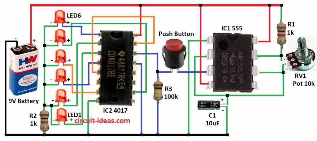
To build a Simple Digital Dice Circuit you need to follow the below mentioned components connections process:
- Gather all the components mentioned in diagram above.
- Connect pin 1 of IC 555 to ground.
- Connect pin 2 and pin 6 of IC 555.
- Connect pin 3 of IC 555 to one leg of push button.
- Connect pin 4 of IC 555 to positive supply of 9V battery.
- Connect pin 6 of IC 555 to one leg of 10k potentiometer.
- Connect pin 7 of IC 555 to one leg of 10k potentiometer.
- Connect pin 8 of IC 555 to positive supply of 9V Battery.
- Connect pin 2 of IC 555 to one end of capacitor C1 and other end to ground.
- Connect resistor R1 between the positive supply and pin 7 of IC 555
- Connect pin 1 of IC 4017 to anode leg of LED 6, Connect pin 2 of IC 4017 to anode leg of LED 2, Connect pin 3 of IC 4017 to anode leg of LED 1, Connect pin 4 of IC 4017 to anode leg of LED 3, Connect pin 5 to pin 15 of IC 4017, Connect pin 7 of IC 4017 to anode leg of LED 4, Connect pin 8 of IC 4017 to ground, Connect pin 10 of IC 4017 to anode leg of LED 5.
- Connect cathode legs of LEDs 2,3,4,5,6 to ground through R2 resistor.
- Connect cathode leg of LED 1 to cathode leg of LED 2.
- Connect pin 13 of IC 4017 to ground.
- Connect pin 14 of IC 4017 to one leg of push button.
- Connect pin 16 of IC 4017 to positive supply of 9V battery.
Safety Measures:
- Handle components carefully.
- Use appropriate tools.
- Double check connections before powering on the circuit.
- If you are unsure about any step, it is always best to consult a more experienced electronics hobbyist or professional.
Conclusion:
By using electronics to produce a random number, a digital dice circuit provides a dependable and entertaining substitute for traditional dice.
Build your own random number generator and showcase your electronic creativity even if it requires soldering and certain electronic components and careful attention to safety.
Leave a Reply