IC 555 is very popular and useful chip in electronics and it works in different modes with bistable, astable and monostable.
Here we used IC 555 in monostable mode to make a Easy DIY Timer Alarm Circuit with 555 IC, also we can set time and after that the buzzer or alarm will ring.
In addition , it is nice project for tasks that need time reminder.
Circuit Working:
Parts List:
| Components | Values | Quantity |
|---|---|---|
| Resistors (All resistors are 1/4 watt unless specified) | 100Ω | 1 |
| 20k | 1 | |
| 470k | 1 | |
| 1M | 1 | |
| 1.5M | 1 | |
| 2.2M | 1 | |
| Capacitors | Ceramic 0.1µF | 1 |
| Electrolytic 470µF | 1 | |
| Semiconductors | IC 555 | 1 |
| Buzzer | 1 | |
| Switches On/Off switch | 5 | |
| Push button (start switch) | 1 | |
| Battery 9V | 1 |
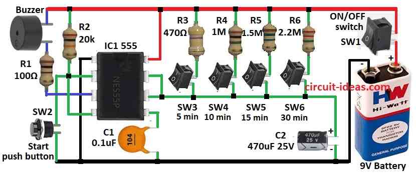
IC 555 stays idle when SW1 turns circuit ON, so choose time by pressing one switch from SW3 to SW6 and this connects to right resistor.
Then press start switch SW2 to trigger IC by grounding pin 2 and capacitor C2 starts charging through selected resistor.
During this time pin 3 is high and so buzzer stays OFF and when capacitor charges up to 2/3 of supply then pin 3 goes low and buzzer turns ON.
As a result, then to reset, press start again or turn power OFF and set a new time.
Formulas and Constructions:
Here, is the formula and calculation for Timer Alarm using IC 555:
Time (T) = 1.1 × R × C
where,
- R resistor chosen by switch R3 to R6
- C is the capacitor value for C2
Calculations:
For R = 470 kΩ and C = 470µF
T = 1.1 × 470,000 × 470 × 10^-6 = 242.99 seconds = 4.04 minutes.
How to Build:
To build a Easy DIY Timer Alarm Circuit with 555 IC we need to follow the below mentioned steps for connections and assembling:
- First, gather all parts as shown in circuit diagram.
- Next, pin 1 of IC 555 connects to GND.
- After that, pin 2 of IC 555 goes one side to pin 4 and other side to GND through Start switch SW2.
- Then pin 3 connects to 9V supply through R1 and buzzer.
- Now pin 4 connects to 9V supply and pin 8 connects to 9V supply.
- Further, pin 5 connects to GND using capacitor C1.
- Also, pin 6 join to pin 7.
- Then switch SW3 to SW6 chooses time by changing resistance R3 to R6 and timing depends on selected resistor and capacitor C2.
- Next, SW1 connects one pin to 9V supply and other to battery positive and battery negative goes to GND.
Conclusion:
To conclude, this is Easy DIY Timer Alarm Circuit with 555 IC in monostable mode and we can change time by using different R and C values.
Also, this circuit is best for beginners to learn how IC 555 works.
Leave a Reply