Make cheap and easy Panic Alarm Button Circuit using IC 555, as this IC 555 work like bistable circuit with two states: alarm ON and alarm OFF.
Pressing the panic button starts the timer, which stays ON until we press the reset button; the timer produces a HIGH output, turns ON the transistor, and activates the LED and buzzer.
Circuit Working:
Parts List:
| Components | Values | Quantity |
|---|---|---|
| Resistors | 10k 1/4 watt | 2 |
| 1k 1/4 watt | 2 | |
| Capacitors | 0.01μF | 1 |
| Semiconductors | IC 555 | 1 |
| Transistor BC547 | 1 | |
| Tactile switches | 2 | |
| LED red 5mm 20mA | 1 | |
| Buzzer | 1 | |
| 9V Battery | 1 |
To begin with, when circuit starts it keep oscillating and give continuous output and circuit parts like R1, R2 and C1 control how fast it oscillate and when alarm goes ON.
How it works:
When power is ON, IC 555 output pin 3 is LOW and buzzer and LED are OFF and transistor BC547 is also OFF with no signal to base.
Then press SET button which is normally open and it connect pin 2 to ground for short time and then this make IC 555 output pin 3 go HIGH and starts the timer.
Furthermore, high signal turn ON the transistor BC547 and then current goes through buzzer and LED and they turn ON and make alarm.
Also, a normally closed button keeps RESET pin 4 HIGH, which keeps the IC 555 ready and the alarm OFF by default.
When we press the RESET button, it disconnects pin 4 from HIGH and resets the IC 555.
The IC then drives the output LOW, which turns off the transistor, as a result, the buzzer and LED stop and the alarm turns OFF.
Formulas:
These are main things and formulas for making set-reset (SR) type IC 555 panic alarm circuit:
1. Trigger Resistor (Rtrigger):
Rtrigger help IC 555 trigger smooth and stop button bounce problem.
Normal value are 1k to 10k oh and these calue depend on button and how sensitive we want it
2. Timing Resistors R1 and R2:
R1 and R2 set how long alarm stays ON or OFF after pressing panic button.
Time formula:
T = 0.693 × (R1 + R2) × C
where:
- R1, R2 are the resistance in ohms Ω
- C is the capacitor in farads F
Note:
This circuit use IC 555 in set-reset mode and if required change R and C values to set right timing for alarm ON and OFF.
How to Build:
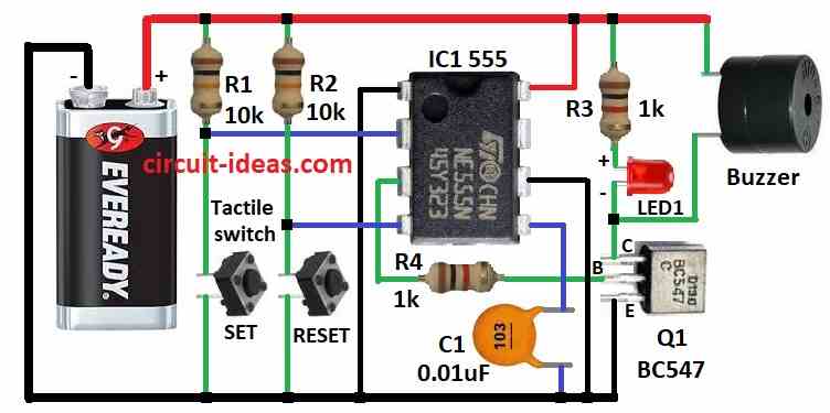
To build a Panic Alarm Button Circuit using IC 555 follow the below mentioned steps for connections:
- First, join all parts as shown in circuit diagram.
- Next, pin 1 of IC 555 connects to ground.
- Then pin 2 connects between resistor R1 and SET push button.
- After that, pin 3 connects to base of transistor Q1 using resistor R4.
- Now pin 4 connects between resistor R2 and RESET push button.
- Also, pin 5 connects to ground with capacitor C1 and pin 6 also connects to ground.
- Lastly, pin 8 connects to +9V battery.
Transistor Q1 Connections:
- Now collector connects to +9V through resistor R3 and LED1, base connects to pin 3 of IC 555 and emitter connects to ground.
- Also, buzzer connects to one end of +9V and other end between LED1 and Q1 collector.
Safety Tips:
- Check all wires and components again to avoid short circuits and damage, also, make sure all resistors, transistors and capacitors can handle the operating voltage.
- Then place LED and capacitor in correct direction and use heat shrink tube or solder wires properly.
- Also, keep circuit safe from water, dust or touch and use plastic box if needed.
Conclusion:
Overall, in this Panic Alarm Button Circuit using the IC 555, pressing the panic button causes the IC 555 to generate an oscillating signal; the signal turns ON the transistor and the buzzer and LED start the alarm.
Finally, press RESET button to stop alarm and reset timer.
Leave a Reply