The Simple Current Limiting Circuit using the LM317/LM338 controls the current flowing to the load and these ICs also work as current limiters when we configure them properly.
Here, power comes in as Vin and LM317/LM338 have 3 pins: input, output and adjust.
Vin goes to input pin ad output pin (Vout) goes to load and gives limited current.
Circuit Working:
Parts List:
| Components | Values | Quantity |
|---|---|---|
| Resistor | Resistor Rx | 1 |
| Semiconductors | IC LM317/LM338 | 1 |
| Heatsink IC LM317/LM338 | 1 |
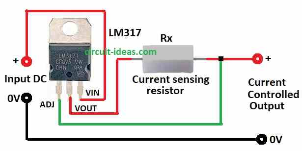
The power source provides the input voltage (Vin), which goes to the input pin of the LM317 or LM338 and the output pin (Vout) connects to the load and supplies a limited current.
Also, one resistor called Rx connects between output and adjust pin and this Rx decide how much current can go to load.
Current limit use this formula:
ILIMIT = VREF / Rx
where,
- ILIMIT is max current goes to load and unit is in amp.
- VREF is the fixed voltage inside LM317/LM338 which usually is 1.25V.
- Rx is the resistor between output and adjust pin its unit is in ohms and this resistor set the current limit.
VREF is inside chip which is usually 1.25V and when load take more current then voltage on Rx goes up.
Therefore, chip see this from adjust pin and lower Vout and this way chip keep voltage on Rx same so current stay same too.
Finally, chip act like smart resistor and control current with feedback.
Important points:
Rx must be strong enough and should not get hot.
Power used by Rx: P = I² × R
LM317 can give max 1.5A and IC LM338 can give 5A and this chip limit current only up to its max limit; also Rx value range is 0.8Ω to 1200Ω which is too low or too high can make chip not work right.
Advantages:
Protect load from too much current and then give steady current, even if input voltage changes a little.
How to Build:
To build a Simple Current Limiting Circuit using IC LM317/LM338 follow the below mentioned steps:
- First, gather all parts like shown in circuit diagram.
- Next, connect adjust pin of LM317 to other side of Rx resistor and this is also current output, connect Vout pin to load through Rx resistor and then connect Vin pin to positive of DC power.
- Also, connect loads negative wire to ground.
Safety Tips:
- Always check LM317 or LM338 datasheet we are using as datasheet tells limits for voltage, current, temperature and safety rules.
- Also, use heat sink, capacitors, resistors with correct ratings and do not give part more voltage or current than it can handle.
- The LM317/LM338 can get hot when the voltage or current is high, so read the datasheet to show whether we need a heat sink, as a heat sink helps cool the IC.
Conclusion:
To conclude, Simple Current Limiting Circuit using IC LM317/LM338 is good to protect our devices from too much current.
So build it carefully, choose good parts, follow safety steps and know how it works; also always check datasheet and stay safe with electronics.
Leave a Reply